First usage – quick start – RME Fireface UCX II 40-Channel USB-B Audio/MIDI Interface User Manual
Page 9
User's Guide Fireface UCX II
© RME
9
5. First Usage
– Quick Start
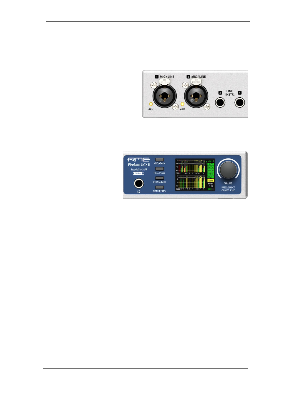
5.1 Connectors
– Controls – Display
The front of the Fireface UCX II features two instrument and microphone inputs, a stereo head-
phone output, a rotary encoder with push functionality, four buttons, a graphical colour display
and two status LEDs.
The Neutrik combo sockets of the two
Mic/Line
inputs provide XLR and 6.3 mm /
1/4" TRS connection. They have LEDs for
phantom power (48V) indication.
Inputs 3/4,
INST/LINE
, accept both a bal-
anced line signal as well as an unbalanced
instrument signal via 1/4" TRS plug.
The analog outputs 7 and 8 feed the headphones output
Phones
. This low impedance output of
highest quality is able to drive headphones at higher levels undistorted, no matter if low or high
impedance headphones are used.
The four
keys
and the
encoder
,
the high-resolution and clear
col-
our display
, and a well thought-
out menu structure enable the
user to quickly change and con-
figure the device’s settings com-
pletely without a computer. Help
notes and clear markers in the
display guide the user through all
functions.
When the Global Level Meter screen is shown, the rotary encoder
sets the monitoring volume of
Main Out directly at the device. Pushing the button will change to Phones volume control, as
indicated in the right lower corner of the screen.
Digital State.
On the right side the main screen shows the current sample rate and the state of
all digital input signals. WCK, SPDIF, AES and ADAT indicate a valid input signal separately for
each digital input. Additionally, RME's exclusive
SyncCheck
indicates if one of these inputs is
locked, but not synchronous to the others, in which case the corresponding field will flash. See
also chapter 8.7 / 14.2, Clock Modes - Synchronization. The field USB will change to CC when in
Class Compliant mode.
State MIDI.
Between ADAT and USB two yellow lines indicate incoming and outgoing MIDI data.