Altera MAX 10 Power User Manual
Page 13
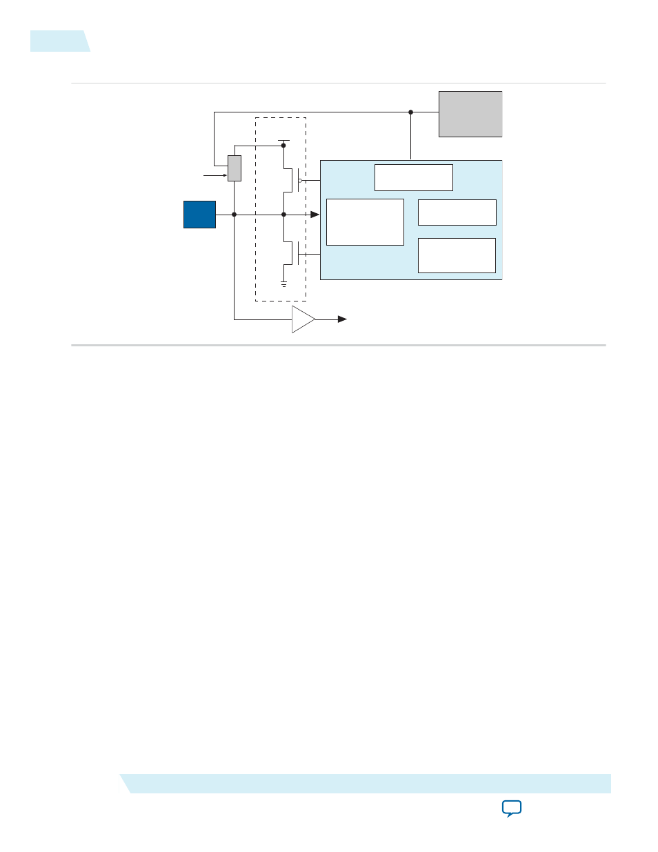
Figure 2-7: Hot-Socketing Circuitry for MAX 10 Devices
VCCIO
PAD
R
Voltage
Tolerance
Control
Output Enable
Hot-Socket
Output
Pre-Driver
Power-On
Reset (POR)
Monitor
Weak
Pull-Up
Resistor
Input Buffer
to Logic Array
The POR circuit monitors the voltage level of power supplies and keeps the I/O pins tri-stated until the
device is in user mode. The weak pull-up resistor in MAX 10 device I/O elements (IOE) keeps the I/O
pins from floating. The voltage tolerance control circuit protects the I/O pins from being driven before
V
CCIO
and V
CC
supplies are powered up. This prevents the I/O pins from driving out when the device is
not in user mode.
Altera uses GND as reference for hot-socketing operation and I/O buffer designs. To ensure proper
operation, Altera recommends connecting the GND between boards before connecting the power
supplies. This prevents the GND on your board from being pulled up inadvertently by a path to power
through other components on your board. A pulled up GND can cause an out-of-specification I/O voltage
or current condition with the Altera device.
2-10
Hot-Socketing Feature Implementation
UG-M10PWR
2015.02.09
Altera Corporation
MAX 10 Power Management Features and Architecture