Power management controller, Entering state, Sleep state – Altera MAX 10 Power User Manual
Page 16: Exiting state, Awake state, Power management controller -3, Entering state -3, Sleep state -3, Exiting state -3, Awake state -3
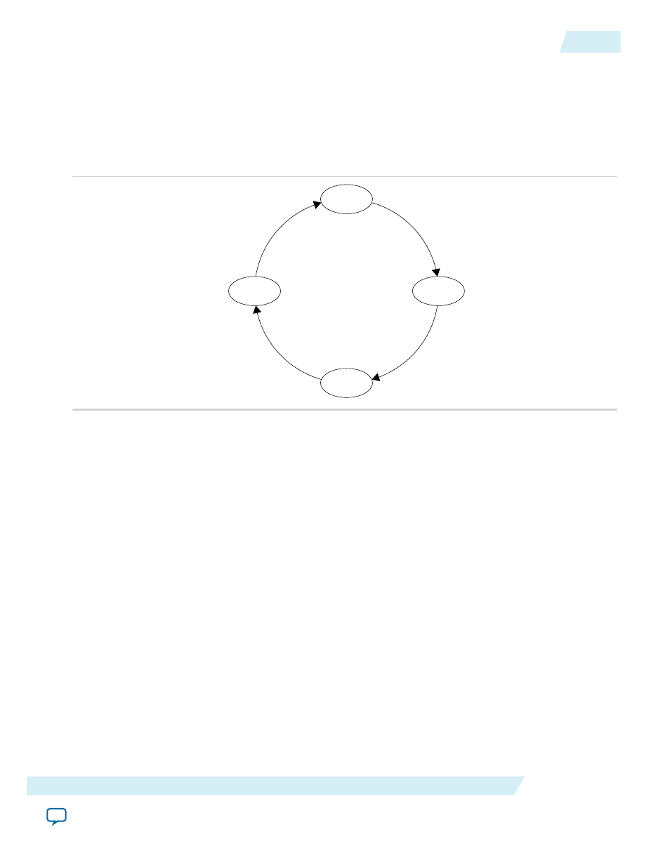
Power Management Controller
The power management controller implements a simple FSM to control the power-up and power-down
sequences of the GCLK networks and I/O buffer. The following figure shows the FSM of the power
management controller design.
Figure 3-2: FSM of the Power Management Controller
Awake
Sleep
Entering
Exiting
Sleep = 1
clk_ena = 1 &
ioe = 1
clk_ena = 0 &
ioe = 0
Sleep = 0
Entering State
When the power management controller detects a sleep event, the FSM transitions to the Entering state
and performs power-down operation on I/O buffers and GCLK networks. A sleep event is detected when
the
sleep
signal is asserted. A sleep event could be triggered by an internal or external request.
Sleep State
After the power-down operation on I/O buffers and GCLK networks, the FSM transitions to the Sleep
state and waits for the wake-up event. This state is the sleep mode state.
Exiting State
When the power management controller detects a wake-up event, the FSM transitions to the Exiting state
and performs power-up operation on I/O buffers and GCLK networks. A wake-up event is detected when
the
sleep
signal is de-asserted. A wake-up event could be triggered by an internal or external request such
as interruption or time-out on some counters..
Awake State
After the power-up operation on I/O buffers and GCLK networks, the FSM transitions to the Awake state.
This process repeats when a sleep event is initiated again.
UG-M10PWR
2015.02.09
Power Management Controller
3-3
Power Management Controller Reference Design
Altera Corporation