General information, General information –25 – Altera Arria V GX FPGA User Manual
Page 47
Chapter 6: Board Test System
6–25
The Power Monitor
July 2012
Altera Corporation
Arria V GX FPGA Development Kit
User Guide
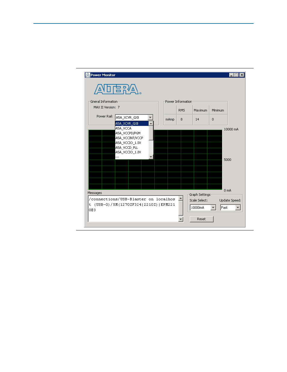
The Power Monitor communicates with the MAX II device on the board through the
JTAG bus. A power monitor circuit attached to the MAX II device allows you to
measure the power that the Arria V GX FPGA is consuming.
shows the
Power Monitor.
The following sections describe the Power Monitor controls.
General Information
The General information controls display the following information about the
MAX II device:
■
MAX II Version
—Indicates the version of MAX II code currently running on the
board. The MAX II code resides in the <install
dir>\kits\arriaVGX_5agxfb3hf40es_fpga\factory_recovery and <install
dir>\kits\arriaVGX_5agxfb3hf40es_fpga\examples\max2 directories. Newer
revisions of this code might be available on the
ge of the Altera website.
■
Power Rail
—Selects the power rail to measure. After selecting the desired rail,
click Reset to refresh the screen with new board readings.
Figure 6–10. The Power Monitor