Factory default switch settings, Figure 4–1 – Altera Audio Video Development Kit, Stratix IV GX Edition User Manual
Page 18
4–2
Chapter 4: Development Board Setup
Factory Default Switch Settings
Audio Video Development Kit, Stratix IV GX Edition User Guide
© November 2009 Altera
Corporation
The MAX II device on the board contains a parallel flash loader (PFL) megafunction.
When the board powers up, the PFL reads one of two designs from flash memory and
configures the FPGA. The rotary switch (SW2) controls which design to load. When
the switch is in the 0 position, the PFL loads the design from the factory portion of
flash memory. When the switch is in the 1 position, the PFL loads the design from the
user portion of flash memory.
1
The development kit includes the MAX II configuration design in the <install
dir>\kits\stratixIVGX_4sgx230_av\examples\max2 directory.
When configuration is complete, the CONF DONE LED (D5) illuminates, signaling
that the Stratix IV GX device configured successfully.
f
For more information about the PFL megafunction, refer to
Factory Default Switch Settings
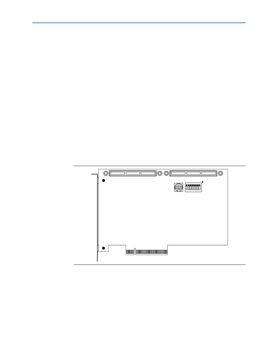
This section shows the factory switch settings for the Stratix IV GX FPGA
development board.
shows the switch locations and the default position of
each switch on the top side of the board.
shows the switch locations and the default position of each switch on the
bottom side of the board.
Figure 4–1. Switch Locations and Default Settings on the Development Board Top
SW3
1
2
3
4
5
6
7
8
ON
0
SW2
Rotary
Switch
ON = 0
OFF = 1
User DIP
Switch