User leds, Push buttons, Capacitor sense button – Altera MAX V CPLD User Manual
Page 17
Advertising
Chapter 5: Board Test System
5–3
Using the Board Test System
January 2011
Altera Corporation
MAX V CPLD Development Kit User Guide
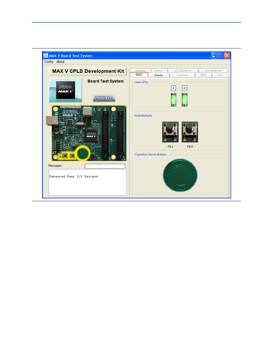
shows the GPIO tab.
The following sections describe the controls on the GPIO tab.
User LEDs
The User LEDs control displays the current state of the user LEDs. Click the LED
buttons to turn the board LEDs on and off.
Push Buttons
The read-only Push Buttons control displays the current state of the board user push
buttons. Press a push button on the board to see the graphical display change
accordingly.
Capacitor Sense Button
The inner circle of the Capacitor Sense Button on the GPIO tab changes to yellow
when you put your finger on the actual capacitor sense button on the board.
Figure 5–2. The GPIO Tab
Advertising