2 led indentification, 1 front leds – Agema AG7448 User Manual
Page 7
4
• Appearance and Mechanism
Chapter 2
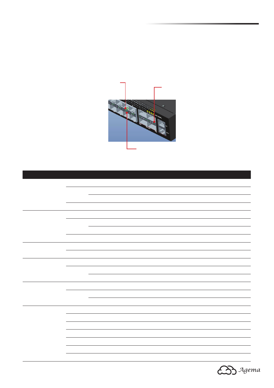
2.2 LED Indentification
This section provides an overview of the front and rear LEDs.
2.2.1 Front LEDs
Upper SFP+ Port LED
Lower SFP+ Port LED
QSFP+ Port LED
(Figure 2-3: Front LED Indentification)
LED
Color
Status
Description
Power
Green
Solid
Both power suppliers presented and operating normally
Yellow
Solid
POST in progress
Blinking One power supply has failed
N/A
OFF
Power disconnected
System
N/A
OFF
No power
Green
Blinking Booting up or running diagnostics
Solid
Normal operation
Red
Solid
Critical system error
Fan
Green
Solid
Fan operating normally
Yellow
Solid
Fan failure
40G QSFP slot
(1x LED per port)
N/A
OFF
No link
Green
Solid
A valid link
Blinking Packet transmission or reception in progress
10G SFP+ slot
(1x LED per port)
N/A
OFF
No link
Green
Solid
A valid link
Blinking Packet transmission or reception in progress
Management slot
(2x LED per port)
Link LED
N/A
OFF
No link
Yellow
Solid
A valid link at 10/100 Mbps
Green
Solid
A valid link at 1000 Mbps
ACT LED
N/A
OFF
No link
Green
Blinking Packet transmission or reception in progress