3 system requirements, 4 data center deployment, 3 system requirements 2.4 data center deployment – Agema AG7448 User Manual
Page 9
6
• Appearance and Mechanism
Chapter 2
2.3 System Requirements
Component
Requirement
System requirements
Switch fabric capacity
Non-blocking full wire speed on all packet sizes
Forwarding architecture
Store and forward or cut-through
Port packet forwarding rate
(at 64 Bytes)
• 14880000 pps (10Gb)
• 1488000 pps (1000 Mb)
MAC address entries
supported
128K entries
Memory type
9 MBytes buffer memory
Console port
Serial RS232 console ports (RJ45)
Serial console
• Provide visual feedback of the boot process to the user
• Timeout after period of inactivity
Port requirements
Speed Capability per Port
1G/10Gbps Auto-Sensing
Full-Duplex Flow Control
Support the IEEE 802.3x PAUSE frame
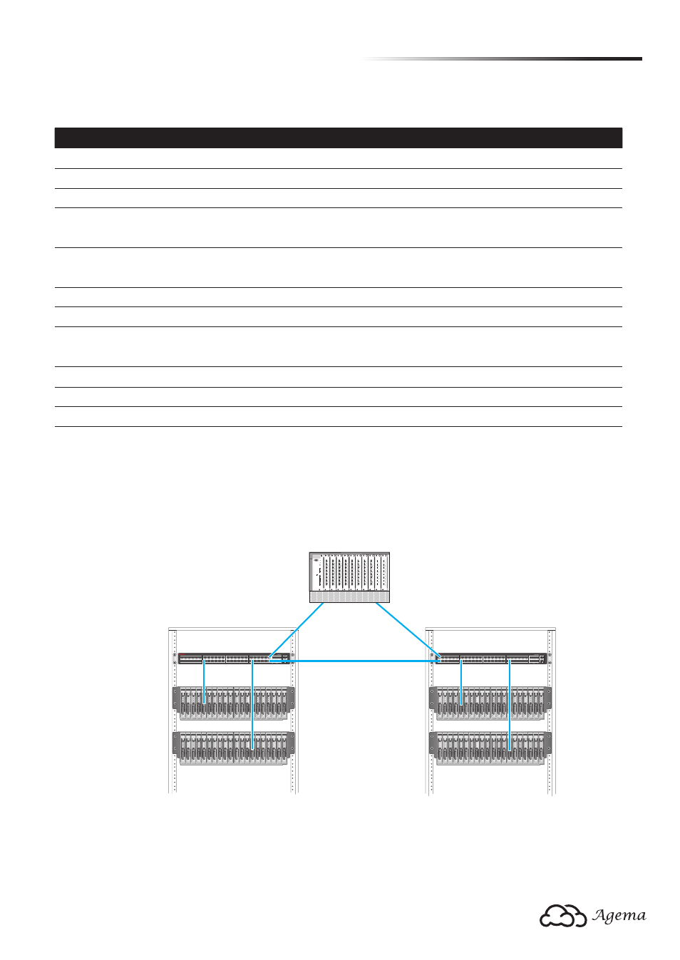
2.4 Data Center Deployment
The following figure illustrates the converaged Ethernet data center deployment.
1
3
5
7
9
11
2
4
6
8
10
12
13
15
17
19
21
23
14
16
18
20
22
24
25
27
29
31
33
35
26
28
30
32
34
36
37
39
41
43
45
47
38
40
42
44
46
48
49
50 51
52
CONSOLE
PWR1 PWR2 SYSTEM FAN
MGMT
AG-7448PL
1
3
5
7
9
11
2
4
6
8
10
12
13
15
17
19
21
23
14
16
18
20
22
24
25
27
29
31
33
35
26
28
30
32
34
36
37
39
41
43
45
47
38
40
42
44
46
48
49
50 51
52
CONSOLE
PWR1 PWR2 SYSTEM FAN
MGMT
AG-7448PL
s
r
e
v
r
e
S
e
d
a
l
B
s
r
e
v
r
e
S
e
d
a
l
B
h
c
ti
w
S
R
o
T
h
c
ti
w
S
R
o
T
Core Switch
Console
Reset
Clear
Mode
Select
Act
Fdx
100
Switch Engine Fail
Self Test
A
X1
Link
Mode
X2
X3
X4
X5
X7
X6
X8
A
X1
Link
Mode
X2
X3
X4
X5
X7
X6
X8
A
X1
Link
Mode
X2
X3
X4
X5
X7
X6
X8
A
X1
Link
Mode
X2
X3
X4
X5
X7
X6
X8
Status
A
I
E
C
1
G
B
J
F
D
2
H
Modules
Power
Fan
A
X1
Link
Mode
X2
X3
X4
X5
X7
X6
X8
A
X1
Link
Mode
X2
X3
X4
X5
X7
X6
X8
A
X1
Link
Mode
X2
X3
X4
X5
X7
X6
X8
A
X1
Link
Mode
X2
X3
X4
X5
X7
X6
X8
A
X1
Link
Mode
X2
X3
X4
X5
X7
X6
X8
A
X1
Link
Mode
X2
X3
X4
X5
X7
X6
X8
(Figure 2-5: Converaged Ethernet Data Center Deployment)