Rack mounting, Back panel – Atlona AT UHD PRO3-88M User Manual
Page 5
5
atlona.com
Toll free: 1-877-536-3976
Local: 1-408-962-0515
EDID
POWER
ENTER
FNC
CANCEL
INFO
1
1
HDMI IN
IR OUT
IR IN
ZONE OUTPUTS
2
3
4
S
S
S
S
S
S
S
S
S
S
S
S
S
S
S
S
5
6
7
8
1ED
2ED
3ED
4ED
5
6
7
9
10
8
2
3
4
9
0
5
6
7
8
AT-UHD-PRO3-88M
IR IN
LAN
FW
RS-232
MAIN
AUDIO OUT
1
2
3
4
5
6
7
9
1
2
3
4
5
6
7
9
6
5
1
2
3
4
5
6
U
se
onl
y wit
h a
250
V
fu
se
G
B20213
746.
5
CN56
8462
TW
M
215
052US
7019
612B
2
PAT.
L
R
L
R
L
4
R
L
3
R
2
1
L
R
L
R
RX TX
S
FUSE: T 4A / 250V
PWR: 100-240VAC 50/60Hz
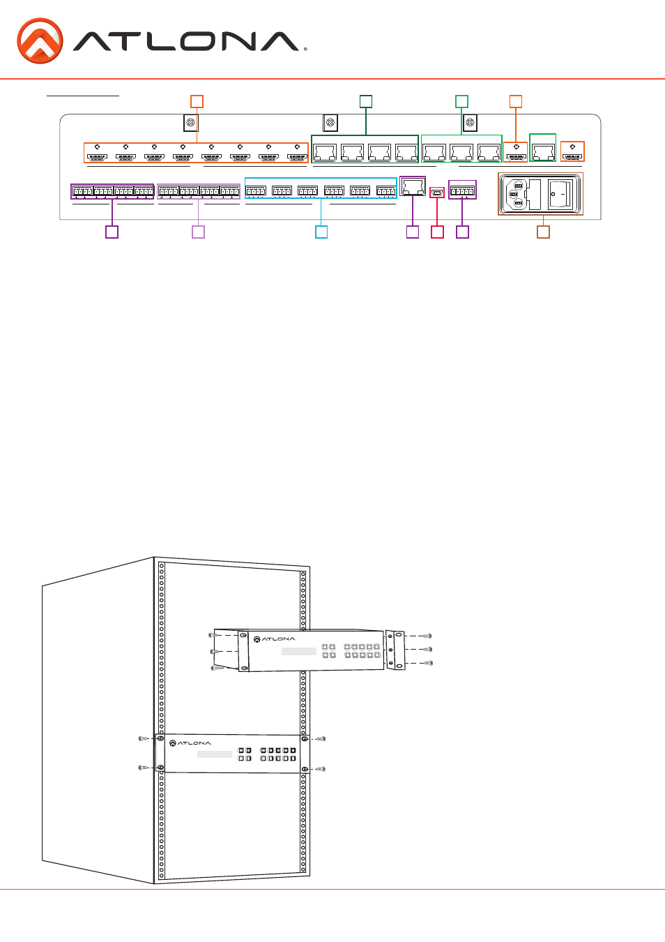
Back Panel
1. HDMI Input - Connect HDMI sources to these ports
Ex. DVD players, Blu-ray players, computers, game consoles, etc
2. Extended distance HDBaseT ports - Connect to extended distance EX receivers for pass through
of PoE, control, and A/V signals. Ex. AT-UHD-EX-100CE-RX
3. Long distance HDBaseT ports - Connect to long distance EX receivers for pass through
of PoE, control, and A/V signals. Ex. AT-UHD-EX-70C-RX
4. HDMI outputs - Mirror to provide a local output for HD audio routing to an AVR, or matrix the
ports to provide a local video output for in room displays or an HDBaseT extender set
Ex. AT-UHD-EX-100CE-KIT
5. IR IN - Use with a 3rd party IR control box to extend IR control commands to video displays over
category cable
6. IR OUT - Connect IR emitter here for controlling sources
7. Audio out - Captive screw analog audio loop outs for use with a sound system or multi-channel
zone amplifier
8. LAN port - Connect to a network for TCP/IP, WebGUI and firmware updates
9. FW port - USB not enabled at this time for future functionality
10. Main control - Connect IR or RS-232 control system to the matrix
11. Internal power supply - Connect included IEC C13 power cable from here to a power outlet.
To rack mount the UHD-PRO3 unit:
use the rack mount ears, the 6
screws from the sides of the UHD-
PRO3, and 4 rack screws.
To affix the rack mount ears,
remove the three screws on each
side of the UHD-PRO3 and affix
the rack ears to the UHD-PRO3 (as
shown in the picture to the left).
Place the UHD-PRO3 in the rack,
lining the holes in the rack ears with
the holes in the rack. Once placed,
use the rack screws to keep the unit
in place. (as shown in the picture to
the left).
Note: Increase the air flow as needed
to maintain the recommended
temperature inside the rack.
Note: Do not exceed maximum weight
loads for the rack. Install heavier
equipment in the lower part of
the rack for stability.
1
2
3
4
5
6
7
8
9
10
11
POWER
ENTER
CANCEL
INFO
EDID
FNC
6
7
8
1
2
3
9
4
0
5
POWER
ENTER
CANCEL
INFO
EDID
FNC
6
7
8
1
2
3
9
4
0
5
Rack Mounting