CIRCUTOR QNA-P Series User Manual
Page 10
Page no.
9
5.1.1.-
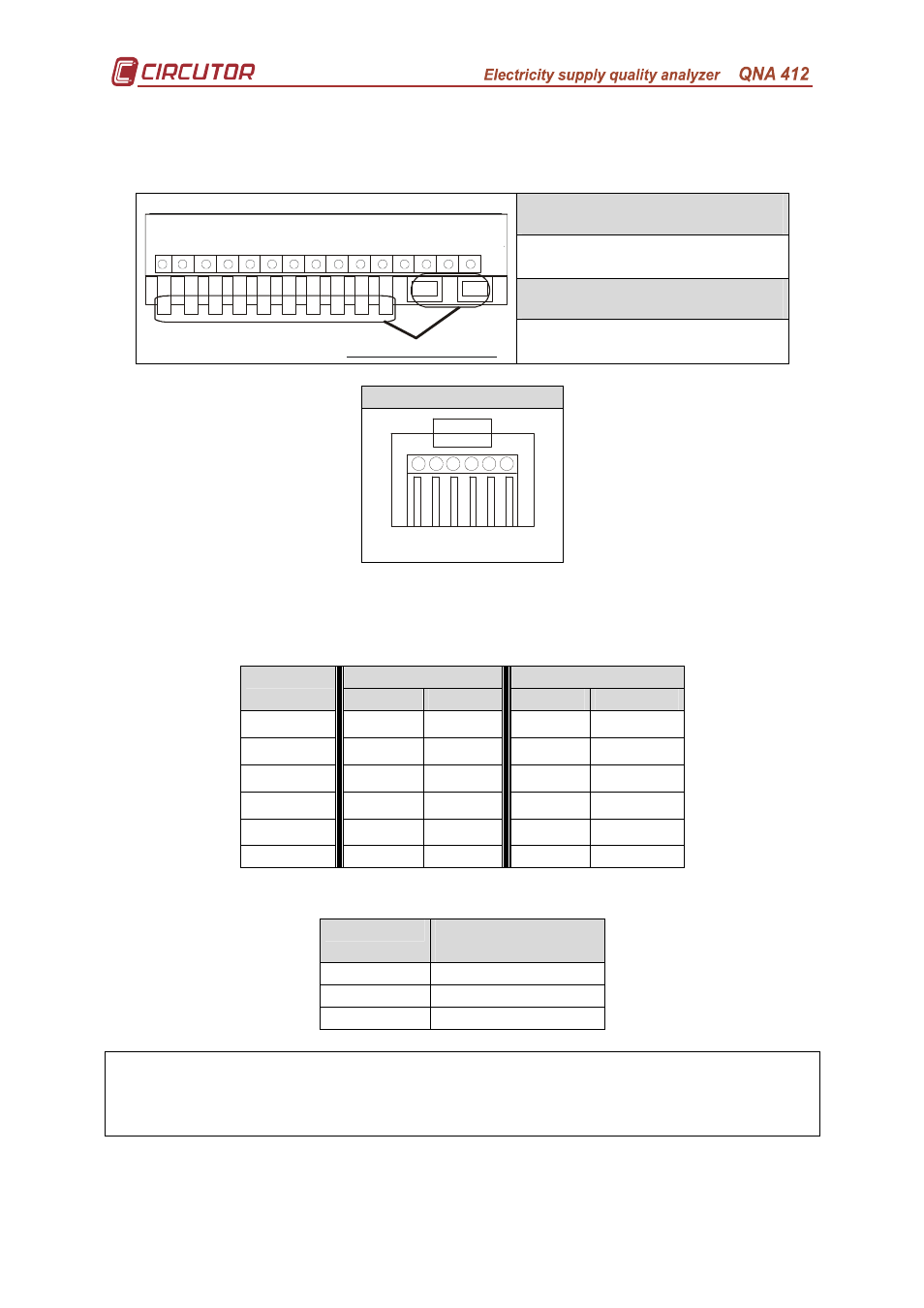
Communications cables for RJ connectors.
The use of the RJ connectors will vary according to the QNA model used.
Therefore:
QNA-412 RS232 / RS485
R1 – RS-232 Communications
R2 – RS-485 Communications
QNA-412 GSM / RS232
R2
R1
1
2
4
3
11
6
5
7
8
9
21
22
24
34
23
33
30
26
31
25
35
27
32
28
29
Lower connec tion terminal
R1 – RS-232 Communications
R2 – GSM aerial
RJ Connector (QNA)
Front view
1
6
2 3 4 5
Below are diagrams of the most usual connections for the QNA-412 communications
cables:
• RS-232 connection to a PC or to an external modem:
PC
External Modem
QNA-412
DB9
DB25
DB9
DB25
1–DSR
5–GND 7–GND 5–GND 7–GND
2–Rx
3–Tx
2–Tx
2–Rx
3–Rx
3–TX
2–Rx
3–Rx
3–Tx
2–Tx
4–CTS
7–RTS
4–RTS
8–CTS
5–CTS
5–RTS
8–CTS
5–CTS
7–RTS
4–RTS
6–GND
5–GND 7–GND 5–GND 7–GND
• RS-485:
QNA-412
RS-232/485 (DB9)
Converter
2–Tx/Rx(-) 2–Tx/Rx (-)
3–Tx/Rx(+) 1–Tx/Rx (+)
6–GND
5–GND
To communicate with a QNA-412-GSM via a mobile telephone, the RS-
232 communications cable must not be connected at any time. If it is detected
that the RS232 cable is connected, any modem operation will be cancelled.