Terminal ratio – CIRCUTOR QNA-P Series User Manual
Page 9
Page no.
8
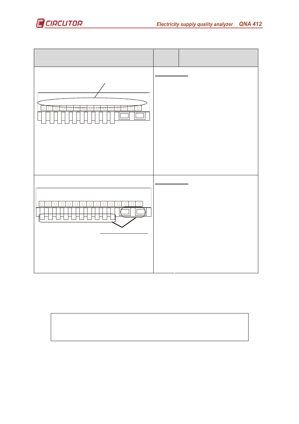
5.1.-
Terminal ratio.
Terminal
No.
Terminal Description
Upper board
21
VL1 measurement
22
Common L1
23
VL2 measurement
24
Common L12
25
VL3 measurement
26
Common L13
27
Neutral
28
Earth
29
Not connected
30
Not connected
31
Not connected
32
Not connected
33
Not connected
34
Not connected
R2
R1
1
2
4
3
11
6
5
7
8
9
21
22
24
34
23
33
30
26
31
25
35
27
32
28
29
Upper c onnec tion terminal
35
Not connected
Lower board
1
Measured current IL1 S1
2
Measured current IL1 S2
3
Measured current IL2 S1
4
Measured current IL2 S2
5
Measured current IL3 S1
6
Measured current IL3 S2
7
Measured current Neutral S1
8
Measured current Neutral S2
9
Voltage input power supply
11
Voltage input power supply
R1
RS-232
R2
R1
1
2
4
3
11
6
5
7
8
9
21
22
24
34
23
33
30
26
31
25
35
27
32
28
29
Lower connection terminal
R2
RS-485 / GSM Aerial
(According to model)
The QNA-412 may be installed in either a three phase system with Neutral (4
wire) or without Neutral (3 wire). Measurement only depends on the connection and
equipment setting.
Earthing is vital to the operation of the QNA-412's
protection.