Connection, rec 3 4 poles and rec 3c 4 poles – CIRCUTOR REC3 Series User Manual
Page 14
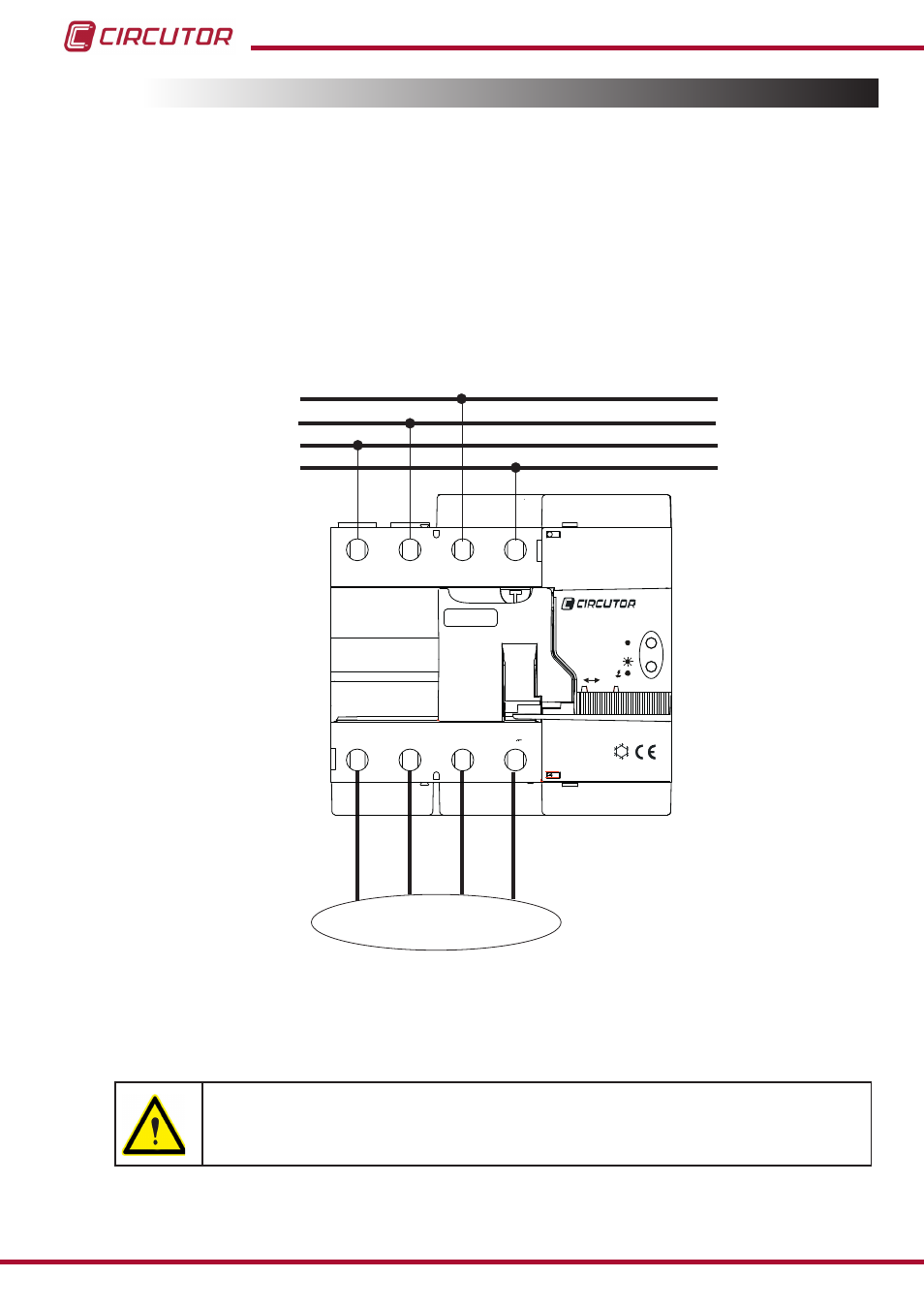
3.4.- CONNECTION, REC 3 4 poles and REC 3C 4 poles
The
REC 3 must be connected to a power circuit protected with miniature circuit breakers, in
accordance with its power supply range and consumption. In turn, the power circuit must be
fitted with a circuit breaker switch or an equivalent device, in order to be able to disconnect
the unit from the power supply mains.
In three-phase installations (the three phases L1, L2 and L3), or three-phase installations with
neutral (L1, L2, L3 and N), the supply cables are connected up top and the cables from the
protected loads are connected below.
If they are wired in reverse order the system will not work.
-25
L1
N
LOAD
L1
L2
L3
L2
L3
N
AUTO
ON
POWER
230V 50Hz
5VA
~;
REC
OFF
EN 50557
Made in EU
REC3
Figure 8: Connection diagram for the REC 3 4 poles and REC 3C 4 poles�
Note: Cross-section of the cable: 16 - 25mm
2
Terminals, opening covers or removing elements can expose parts that are
hazardous to the touch while the unit is powered
14
Instruction Manual
REC 3 - REC 3C