Outputs: rec 3c 2 poles and rec 3c 4 poles – CIRCUTOR REC3 Series User Manual
Page 15
If the
TELE REC 2 indicates a permanent failure (AUTO and REC LEDs are
lit), you must check the RCCB and the installation
If the installation of the unit is done with the RCCB in the OFF state, when panel
receives voltage the unit will not activate the automatic reclosing system for sa-
fety reasons. The
AUTO and REC LED turn on after a few seconds. A manual
reclosing of the system must be done on the panel with voltage.
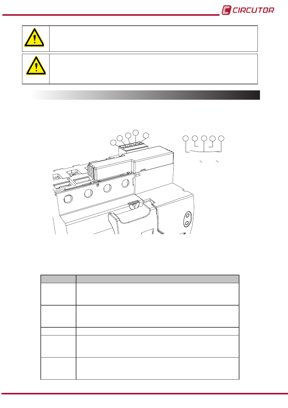
3.5.- OUTPUTS: REC 3C 2 poles and REC 3C 4 poles
Figure 9 we see the connection of the 2-pole changeover contacts on the REC 3C 2 poles
and
REC 3C 4 poles
5
4
3
2
1
230 V 0,13 A
5
4
3
2
1
Figure 9: Connection of pole changeover contacts for the REC 3C 2 poles and REC 3C 4 poles�
Pole changeover contact terminals
Table 2,
Table 2:Pole changeover contact terminals for the 4-pole and 4-poles REC 3C
Terminals
Description
1
Contact in locked status.
NO Status: indicates that the unit has been locked.
NC Status: indicates that the unit has not been locked.
2
Contact in locked status,
NO Status: indicates that the unit has not been locked.
NC Status: indicates that the unit has been locked.
3
Terminal shared by the two contacts.
4
Contact in RCCB position status.
NO Status: indicates that the RCCB status is OFF
NC Status: indicates that the RCCB status is ON
5
Contact in RCCB position status.
NO Status: indicates that the RCCB status is ON
NC Status: indicates that the RCCB status is OFF
15
Instruction Manual
REC 3 - REC 3C