CIRCUTOR EMK Series User Manual
Page 12
EMK
series
Instructions Manual M98118701-01-12A 12
•
The rated current of the CT primary winding must be equal to or slightly greater than the size
of the installation's main switch. The CT must be able to measure the maximum forecast
current expected to be consumed by all the loads.
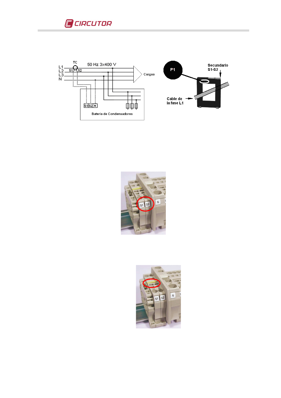
Fig. 5-1 .- Installation of the current transformer (CT) (external)
•
The connection point of the CT for a bank that compensates an entire installation is after the
installation's main switch.
•
To prevent excessive attenuation of the CT signal, the minimum cross section of the cable
connecting the secondary of CT to terminals S1-S2 in the capacitor bank, must be at least 2.5
mm
2
.
Fig. 5-2 .- CT and neutral connection terminals if required
•
Once the CT cables are installed, disconnect the jumper connecting terminals S1 and S2 on
the capacitor bank (see Fig. 5-3)
Fig. 5-3 .- Jumper for short-circuiting the secondary winding of the current transformer (CT).