CIRCUTOR EMK Series User Manual
Page 14
EMK
series
Instructions Manual M98118701-01-12A 14
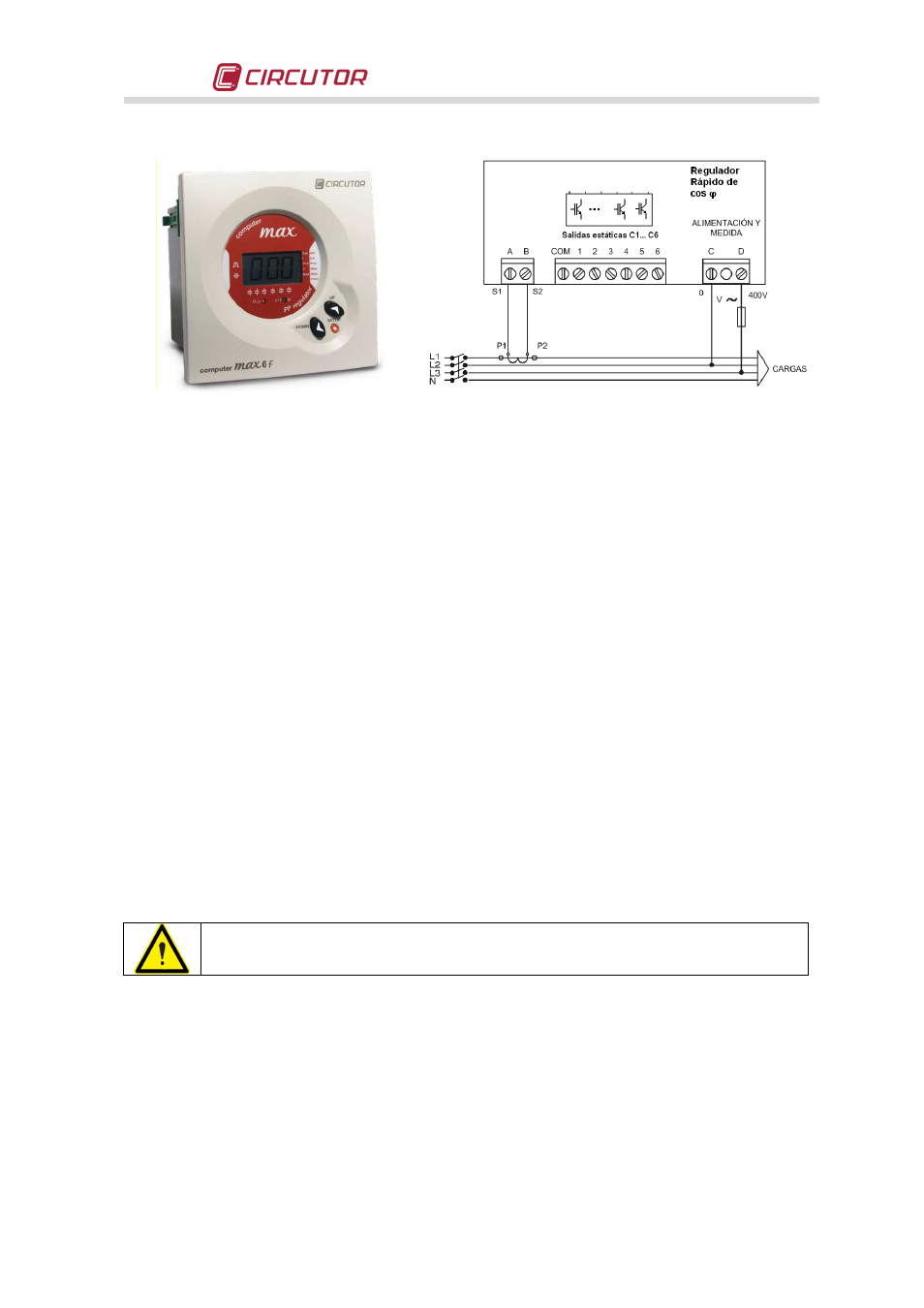
Fig. 6-1 .- Computer Max f regulator
(Picture provided as an example. It may not
coincide with the model used on your unit).
Fig. 6-2 .- Connection of a regulator with only one CT
(If using computer PLUS, 3 current transformers are used. See the
specific manual of the computer PLUS regulator)
•
Once ensured that the regulator is properly connected, adjust the regulator parameters for the
installation you are attempting to compensate. For this, follow the instructions of the particular
PF regulator manual, supplied with the equipment.
6.3
Tests once the capacitor bank is connected and the regulator has been adjusted
•
After start-up, make sure that the equipment is operating properly. A sign of proper operation,
once the steady state of the regulator has been reached, is a cos
ϕ
indication on the display
close to 1. In addition, the reactive energy meter should stop counting.
•
Check that the power supply voltage does not exceed the nominal value +10% (IEC 60831-1)
•
Check the current absorbed by each capacitor step. Under normal working conditions, it must
be close to the nominal values (see Table 6.4) and never more than 1.3 times this value. A
permanent consumption in all the capacitor steps over the nominal value, may be caused by
the presence of harmonics in the grid or by an excessively high power supply voltage. Both
circumstances are harmful for capacitors and control panels. If there is an unusual
consumption in only some of the capacitors, it is a sign that there are damaged capacitors.
•
In accordance with the IEC 60831-1 Standard, the capacitors are prepared to operate at the
permanent voltage assigned and with an overvoltage of up to 10% during 8 hours every 24
hours.
Check the working temperature of the capacitors after they have been operating for
24 hours. The capacitor case must be under 40ºC.