Sensor functionality – CP Electronics VITP-MWS3A User Manual
Page 2
2
When movement is detected the detector sends a signal to the VitessePlus marshalling box (LCM). The LCM is
programmed to either, turn on the load (Presence) or the load is manuallly turned on via a switch (Absence). When the
area is no longer occupied the load will automatically switch off after an adjustable time period.
Sensitivity to movement of the microwave sensor can be adjusted using the Sensitivity parameter.
HINT: To assist in setting the Sensitivity, turn on the Walk Test LED which will flash red when movement is detected.
Switch Level On/Off (with non-dimming LCMs only)
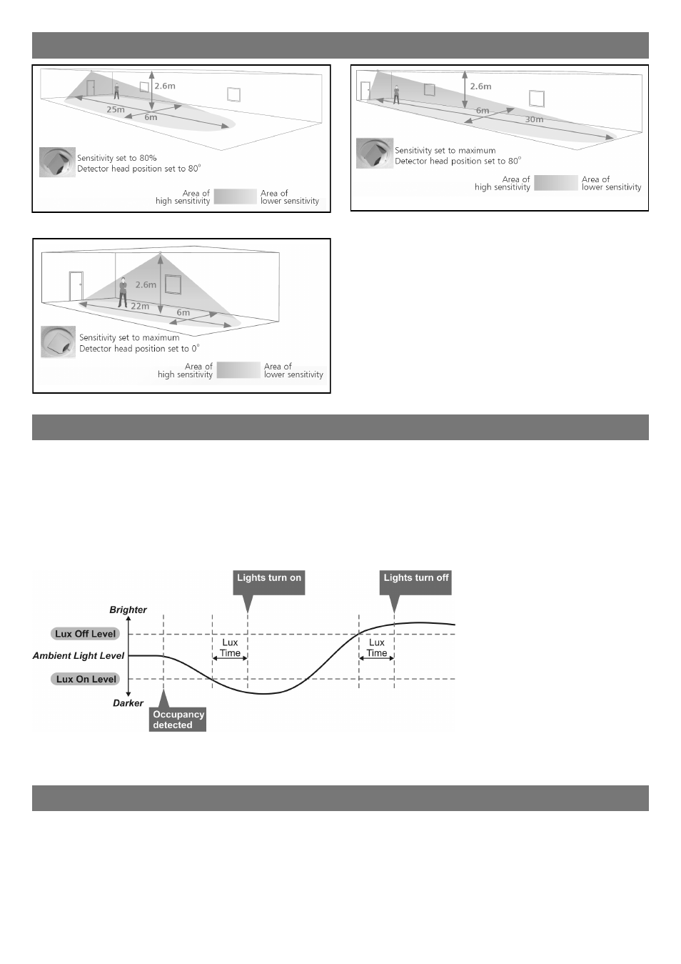
Occupancy detection can be made dependant on the ambient light level using the Lux On Level and Lux Off Level
parameters. See page 7 for programming details.
Maintained Illuminance (with dimming LCMs only)
The detector measures the overall light level in the detection area and calculates the correct output for the luminaires, to
achieve a preset lux level (maintained illuminance).
Sensor functionality
Overview
It is a requirement of many fluorescent lamp manufacturers to have the lamps on at maximum output for a period of time
to guarantee lamp life (refer to the manufacturer’s datasheet for details) As this VITP-MW3A is able to dim the lamps via
the VitessePlus LCM (lighting control module), the product provides a facility to disable this for a given period of time.
Operation
By setting the “Burn in” parameter, you can select a time during which the lamps are not allowed to deviate from
maximum output. The unit counts the time, and even remembers how long has elapsed in the event of a power failure.
To cancel the burn in function, simply select a time of 0. Note that when the lamps are changed, the burn in time should
be set again.
Burn-in (with dimming LCMs only)
Detection diagrams
Ideal for large office or classroom
Ideal for corridor or aisle applications
Ideal for open plan areas and offices
Note. If the range is compromised by the ceiling construction /
material. Add the supplied 20mm spacer ring. See page 3 for
fitting details.