Connecting, Power, input and output connection – CUE relayCUE-8 User Manual
Page 7
3. Connecting
The enclosure of relayCUE-8 allows simple installation into switchboard on DIN rail.
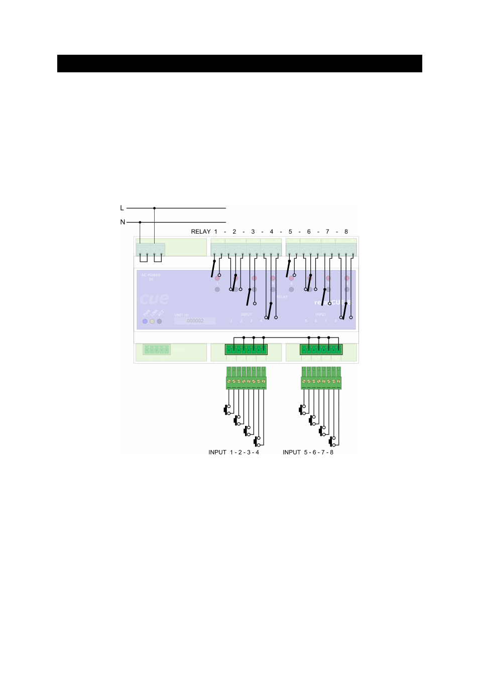
3.1............................Power, input and output connection
Eight digital contact closure inputs are connected via two 8-pin connectors Phoenix 3,5 mm. Every
input has 2 terminals – the first is input signal, the second is input common (ground).
Eight relays are connected via screw-type terminal (up to 1.5 mm
2
wire). Four relays have two
terminals C-NO (Common – Normaly Open), 230 V, max. 10 A (resistive load), four relays have three
terminals NC-C-NO (Normaly Close – Common – Normaly Open), 230V, max. 10A (resistive load).
AC Power input is connected via four screw-type terminals (up to 1.5 mm
2
wire). Two terminals are L
(Live), two terminals are N (Neutral). A connection of the relays, power and contact closure inputs is
described on the picture below.
All relays are open in this picture.
Important note:
The relay contacts in relayCUE-8 are constructed for resistive load up to 230V/10A. If these
relays are used for the switching of inductive (or capacitive) loads, voltage or power peaks can
occur, which may exceed these parameters even if the load has the stated take-off lower than
230V/10A. We therefore do not recommend using relayCUE-8 for switching inductive or
capacitive loads with take-off higher than 400W.
If you need to switch higher loads, use contactors. Unlike relays, contactors are designed with
features to control and suppress the arc produced when interrupting inductive load currents.
You can then use the relay of the relayCUE-8 unit to control the coil of this contactor.
User Manual relayCUE-8
www.cuesystem.com
Page 7 of 24