Thor 2 mW CATV RF Over Fiber Tx 45-870 MHz User Manual
Page 4
4
16mW
52.0
51.0
50.1
49.1
48.1
18mW
52.5
51.6
50.6
49.7
48.7
47.9
20mW
51.9
51.0
50.0
49.0
48.0
22mW
52.2
51.4
50.4
49.4
48.6
47.8
24mW
51.5
50.3
49.2
48.5
47.7
26mW
51.5
50.2
49.2
48.5
47.6
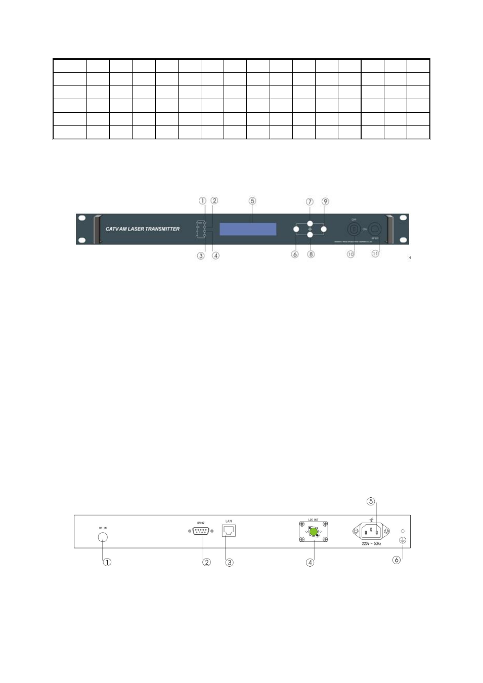
5. Exterior function explanation
5.1 Front panel description
Front panel sketch map
1.
Power indicator: when the power inside is working, the light is on.
2.
Equipment operating indicator: equipment works: LED blinks by 1Hz frequency.
3.
LD laser operating status indicator: red light shows that the laser does not work and each
parameter is normal; when the red light is flashing, it shows that this equipment is at fault.
The faulted reason can be looked up in the alarm list of the show menu. When the green light
is on, it shows that laser is working normally.
4.
RF status indicator: Green light: normally operation; Red light: laser abnormity.
5.
The 160×32 crystal liquid display: this displays all parameters.
6.
Withdraw or cancel key.
7.
Up and increase key.
8.
Down and decrease key.
9.
Confirmation key
10. Laser switch key: Control work status of the laser. “ON” indicate laser is turn on, “OF”
indicate laser is turn off. When powering on the unit, the key must be OFF, after power on
self test, the laser can be turned on when the display indicates the unit is ready.
11. Input RF signal Test port: -20dB RF Test Port
5.2 Back panel explanation
Back panel elucidation
1.
RF input
2.
RS232 interface: use for various network management parameter allocations.
3.
LAN interface: match with IEEE802.3 10Base-T interface, use for network management.