Argox A Series User Manual
Page 40
A Series User’s Manual
79
3.
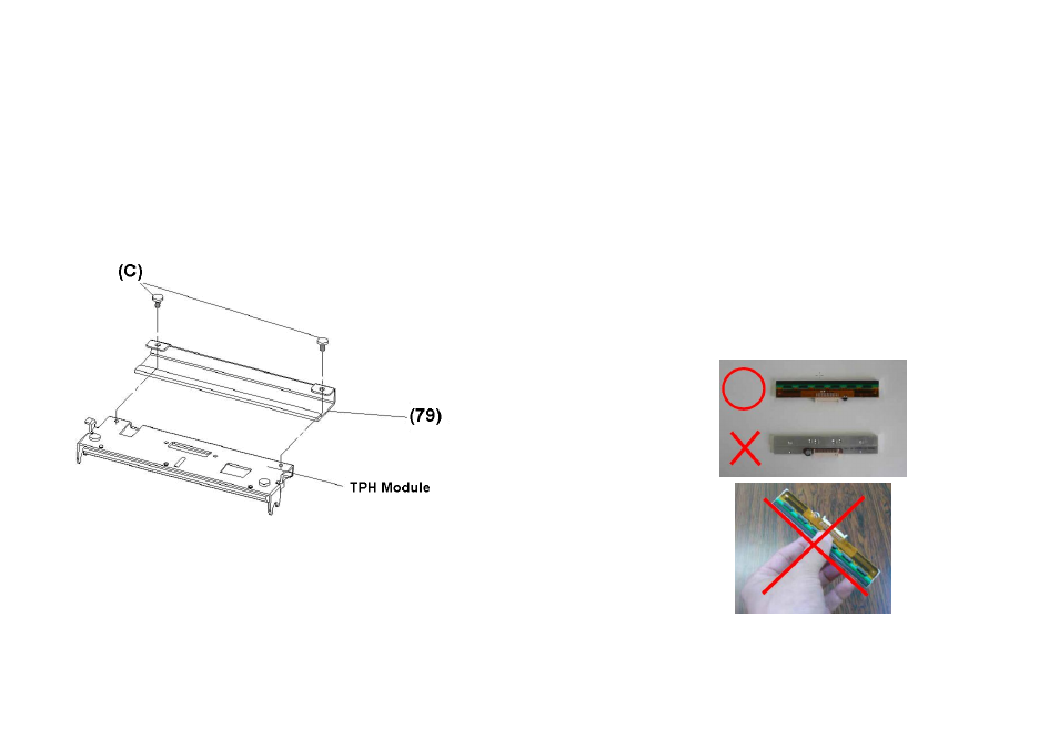
Loosen the 2 screws(C) and take off COVER-TPH(79)
4.
Unplug the 2 print head cables from the connectors on the
old TPH-module.
5.
Plug the 2 print head cable to the new TPH-module.
6.
Screw the COVER-TPH (79).
7.
Put the new “Print Head module” onto “Printer Chassis” with
the same way, which you released it from “Printer Chassis
A Series User’s Manual
80
Important notice during TPH replacement
1. Heater line should NOT be touched by bare hands to
prevent any damage caused by ESD or corrosion.
2. Surface of heaters should NOT be hit or scratched by
sharp or hard things to prevent any damage by
scratch.
3. Residue or contamination should NOT be removed
by a cutter to prevent any damage by dent or scratch.
4. Connector side should NOT be touched when
cleaning TPH to prevent delaminated solder between
FPC and wafer. Ink-jet characters could be erased, if
cleaning cloth was touched them on FPC or label.
5. Heater surface should be free from any
condensation.
6. TPH should NOT be put heater surface down.