Rear panel, Tm722a/b/s rear panel, Tm722g rear panel – ARRIS TM722G-CT User Guide User Manual
Page 22: Front pane, Tm722a/b/s front pane, Tm722g front panel
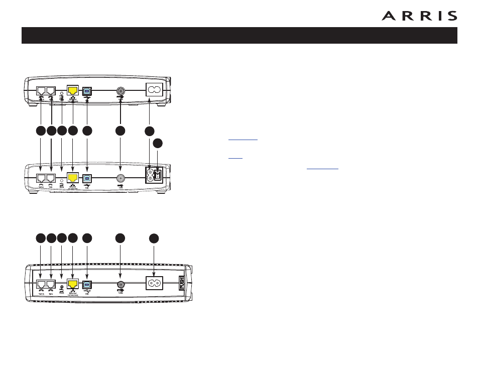
Rear Panel
The rear of the Telephony Modem has the following connectors and controls:
TM722A/B/S Rear Panel
A Tel 1 (grey): connector for the first phone line.
B Tel 2 (grey): connector for the second phone line.
C Reset button: resets the Telephony Modem as if you power cycled the unit.
Use a pointed non-metallic object to press this button.
D
connector (yellow): for use with a computer or home network LAN
connection.
E
connector (blue, if equipped): for use with a computer USB connection.
G Power: connector for the power cord.
H Power Switch (TM722S only): power On/Off switch.
TM722G Rear Panel
A Tel 1/2 (grey): connector for the first phone line (or both lines of a 2-line
phone).
B Tel 2 (grey): connector for the second phone line.
C Reset button: resets the Telephony Modem as if you power cycled the unit.
Use a pointed non-metallic object to press this button.
D Ethernet connector (yellow): for use with a computer or home network LAN
connection.
E USB connector (blue, if equipped): for use with a computer USB connection.
F Cable: connector for the coax cable.
G Power: connector for the power cord.
Touchstone TM722 Telephony Modem User’s Guide
22
A
C
B
D
F
E
G
TM722G
TM722A/B
H
TM722S
A
C
B
D
F
E
G