Figure 3-22, P30 backplane connector pinout - rows a to d, Figure 3-23 – Artesyn ATCA-7365-CE Installation and Use (May 2014) User Manual
Page 87: P30 backplane connector pinout - rows e to h, Controls, indicators, and connectors
Advertising
Controls, Indicators, and Connectors
ATCA-7365-CE Installation and Use (6806800L73J)
87
SAS Update channels
General control signals (BD_PRESENTx, RTM_PRSNT_N, RTM_RST_KEY-, RTM_RST-)
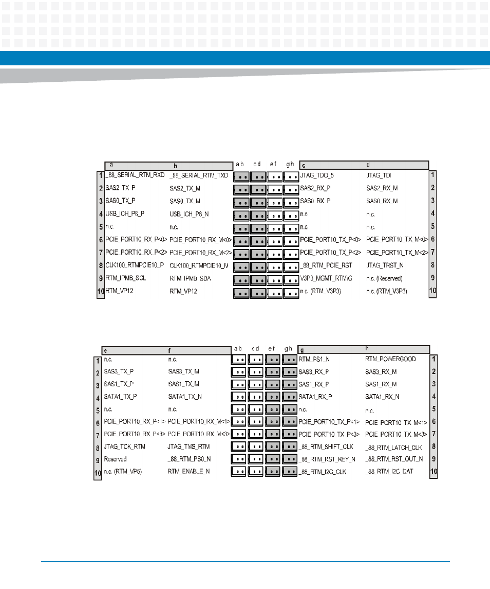
Figure 3-22 P30 Backplane Connector Pinout - Rows A to D
Figure 3-23 P30 Backplane Connector Pinout - Rows E to H
Advertising
This manual is related to the following products: