2 configuration header, Figure 2-11, Configuration header, j9 – Artesyn ATCA-9305 User's Manual (May 2014) User Manual
Page 61: Om. see
Setup
ATCA-9305 User’s Manual (10009109-07)
61
P0800, P0801: These 5 pin horizontal mini-B USBs are the CN5860 consoles which are valid for
PCB Rev. 2.x boards.
2.2.2
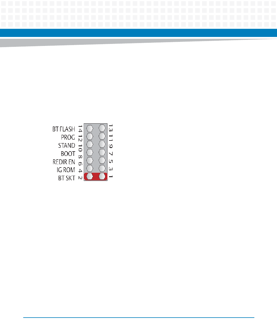
Configuration Header
There are a total of seven jumper pairs on J9 (pins 11-14 are spare posts). See
for the
jumper location on the ATCA-9305. Also reference the “Jumper Settings (0x18)” register.
BT SKT: A shunt on pins 1-2 selects the 512 KB socketed ROM as the boot device for the
MPC8548.
IG SROM: If the serial ROM configuration jumper is installed (pins 3-4), the ATCA-9305 will not
try to configure (IGNORE_SROM*) from the MPC8548 serial ROM.
REDIR EN: A shunt installed on pins 5-6 disables the boot redirection, see
for more
information.
BOOT: A shunt on pins 7-8 causes both Cavium CN5860s to boot from their local bus and not
boot over PCI.
STAND: A shunt on pins 9-10, IPMC stand alone mode, allows the board to boot without
management control.
PROG: Installing a shunt on pins 11-12 puts the IPMC controller into programming mode. This
is only used in the factory to configure the IPMC.
Figure 2-11 Configuration Header, J9