Controls, LEDs, and Connectors
MVME4100 Single Board Computer Installation and Use (6806800H18G)
48
3.2
Board Layout
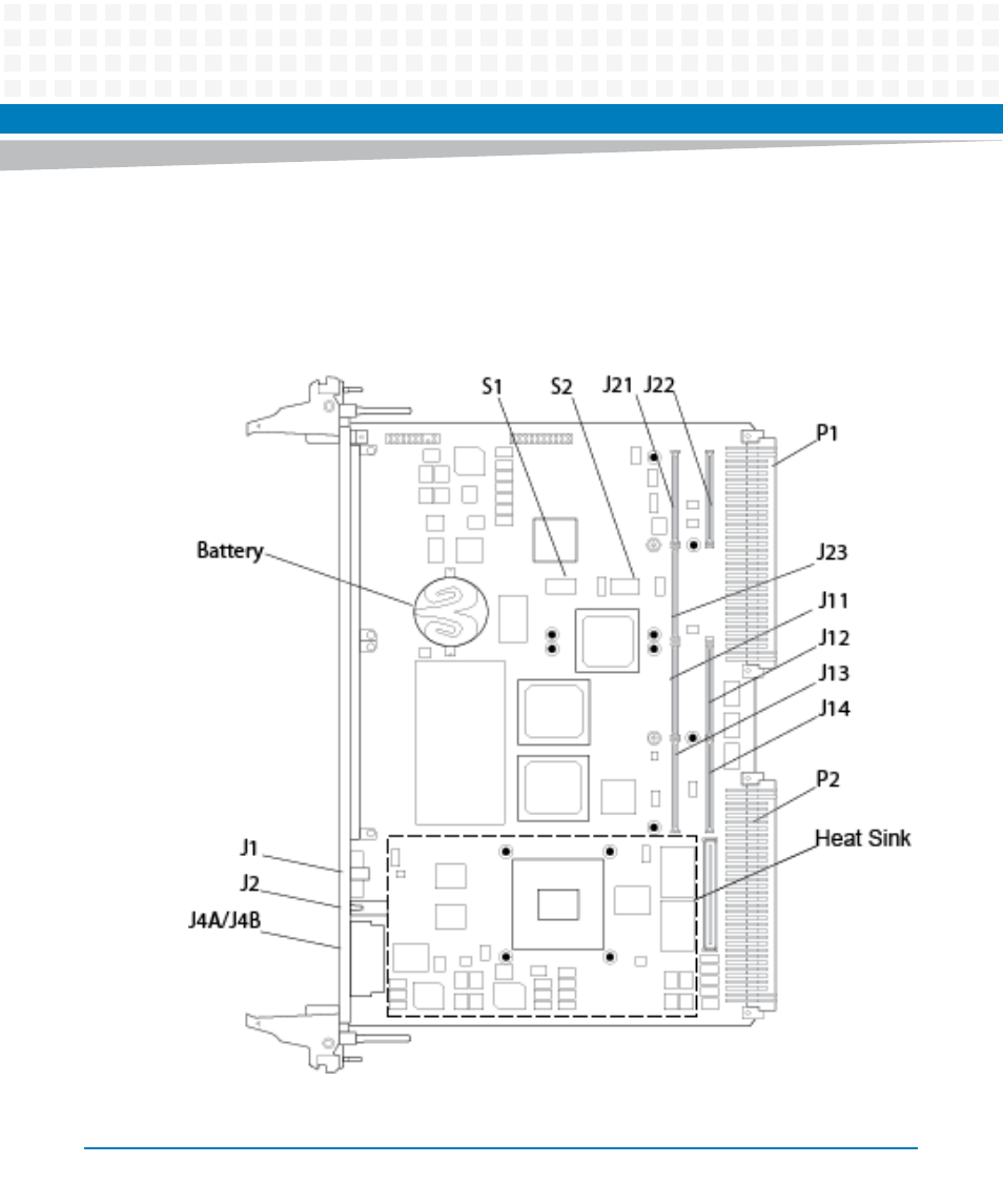
The following figure shows the components, LEDs, connectors, and the reset switch on the MVME4100.
Figure 3-1
Component Layout