2 leds, Table 3-1, Front panel leds – Artesyn MVME4100 Single Board Computer Installation and Use (June 2014) User Manual
Page 50: Controls, leds, and connectors
Controls, LEDs, and Connectors
MVME4100 Single Board Computer Installation and Use (6806800H18G)
50
3.3.2
LEDs
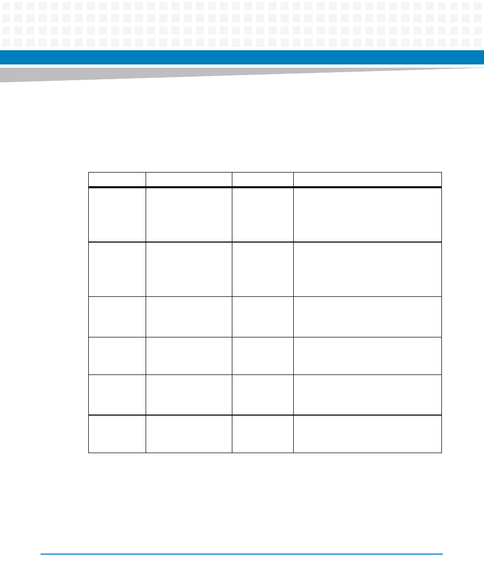
The next table describes the LEDs on the front panel of the MVME4100. Refer to
for LED locations.
Table 3-1 Front Panel LEDs
Label
Function
Color
Description
BFL
Board Fail
Red
This indicator is illuminated during a hard
reset and remains illuminated until
software turns it off. The LED is
controlled by bit 14 (BDFAIL) of the
VSTAT register in the Tsi148.
USR1
User Defined
Red/Yellow
This indicator is illuminated by S/W
assertion of its corresponding register
bits in the Status Indicator Register. See
the Programmer's Guide for further
details.
GNET1 SPEED
TSEC1 Link / Speed
Off
Yellow
Green
No link
10/100 BASE-T operation
1000 BASE-T operation
GNET1 ACT
TSEC1Activity
Off
Blinking Green
No activity
Activity proportional to bandwidth
utilization
GNET2 SPEED
TSEC2 Link / Speed
Off
Yellow
Green
No link
10/100 BASE-T operation
1000 BASE-T operation
GNET2 ACT
TSEC2 Activity
Off
Blinking Green
No activity
Activity proportional to bandwidth
utilization