Table 3-10, Pmc slot 2 connector (j22) pin assignments, Controls, leds, and connectors – Artesyn MVME4100 Single Board Computer Installation and Use (June 2014) User Manual
Page 61
Advertising
Controls, LEDs, and Connectors
MVME4100 Single Board Computer Installation and Use (6806800H18G)
61
55
AD04
GND
56
57
+3.3V (VIO)
AD03
58
59
AD02
AD01
60
61
AD00
+5V
62
63
GND
REQ64#
64
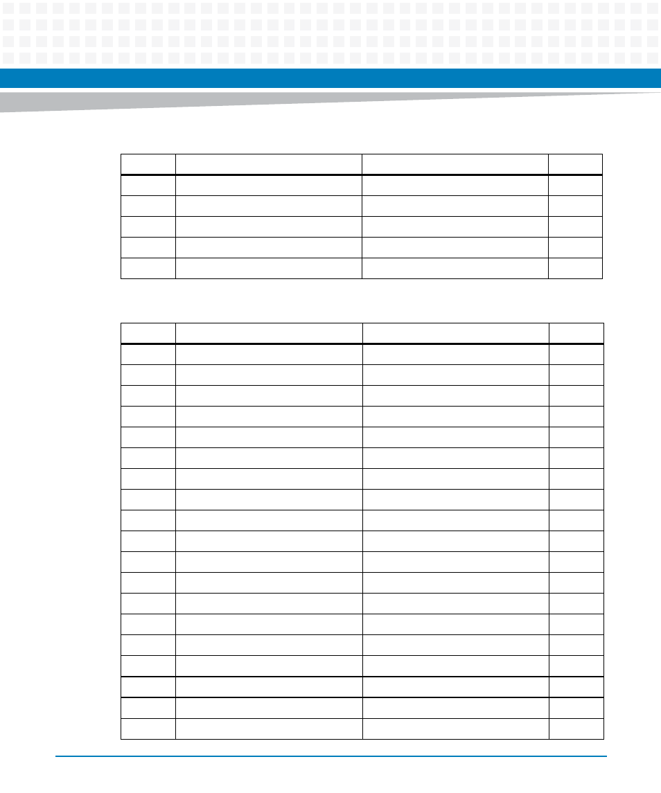
Table 3-10 PMC Slot 2 Connector (J22) Pin Assignments
Pin
Signal
Signal
Pin
1
+12V
TRST#
2
3
TMS
TDO
4
5
TDI
GND
6
7
GND
Not Used
8
9
Not Used
Not Used
10
11
Pull-up to +3.3V
+3.3V
12
13
RST#
Pull-down
14
15
+3.3V
Pull-down
16
17
Not Used
GND
18
19
AD30
AD29
20
21
GND
AD26
22
23
AD24
+3.3V
24
25
IDSEL1
AD23
26
27
+3.3V
AD20
28
29
AD18
GND
30
31
AD16
C/BE2#
32
33
GND
IDSEL1B
34
35
TRDY#
+3.3V
36
37
GND
STOP#
38
Table 3-9 PMC Slot 2 Connector (J21) Pin Assignments (continued)
Pin
Signal
Signal
Pin
Advertising