Zone controller eprom replacement, Philips – Auto-Zone Control Systems EZ-Zone to Auto-Zone Upgrade Guide (Version 01C) User Manual
Page 28
EZ Zone/Auto-Zone
28
Upgrade
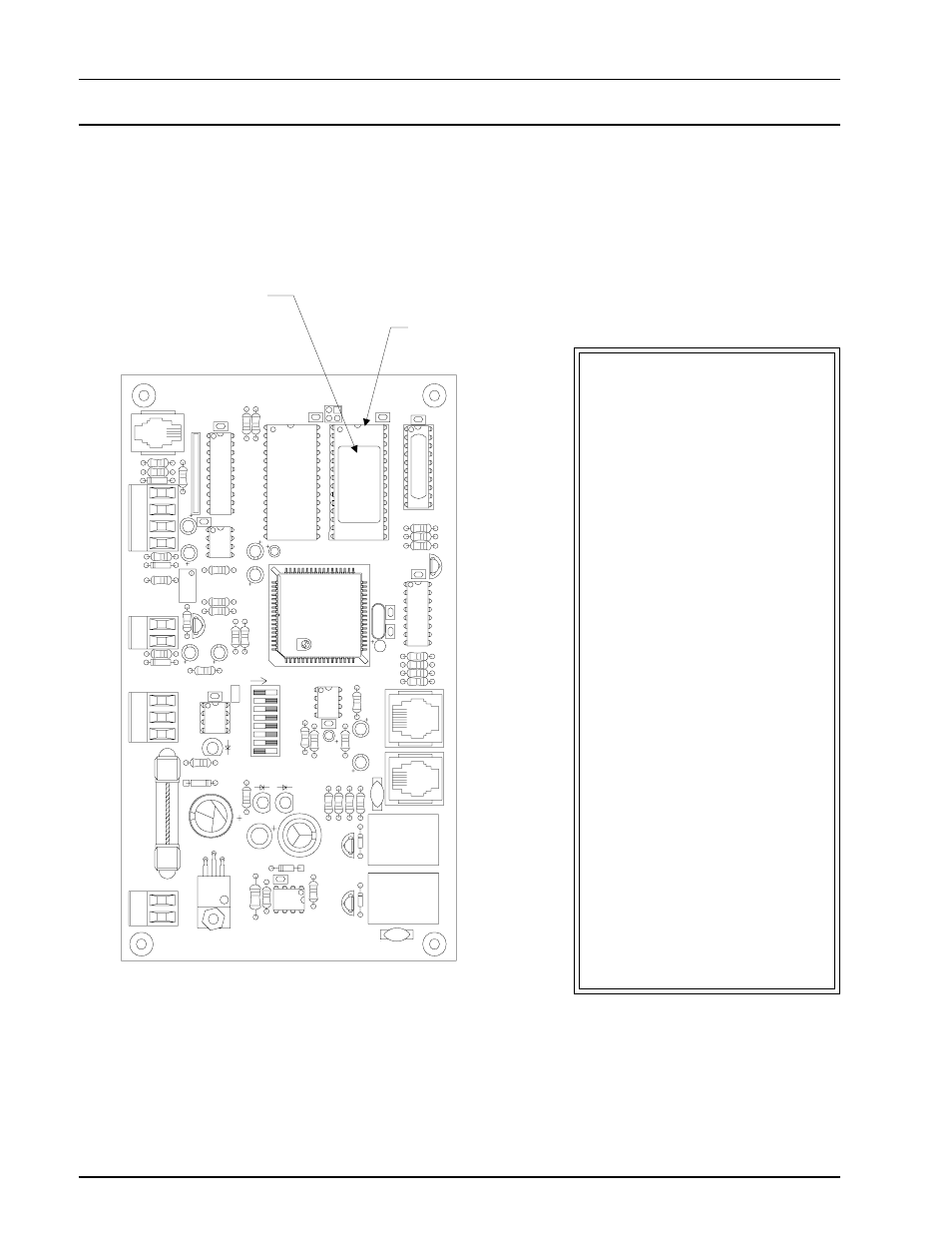
Figure 16: EZ Zone Zone Controller EPROM Location
Zone Controller EPROM Replacement
CX6
SW1
U10
75176
EXP
AN
SION
Q3
Q2
D3
VR1
7824
GND
24VAC
M
7824C
T
MC340
64A9936
R17
R16
U7
C7
R15
POWER
R21
REV
.2
YS101
562
MDL
F1
250
D4
R26
LD3
L1
SCAN REC
R12
C6
R1
1
TOKEN
NET
LD2
32
R14
R13
R100
LD1
C5
D1
K1
V2
24VDC
CONTACT:
UL / CSA 5A250VAC
K2
D2
ACTUA
TO
R
24VDC
CONTACT:
UL / CSA 5A250VAC
R10
R9
PJ2
V1
C4
74HC573N
B31920PS
TCU32K2V
9936
MS6264L-70PC
EPROM
VREF
ADJ
R23
C10
PCB80C552-5-16WP 500650=1/3 DFD9940SM
PHILIPS
EWDOG
COMM
D7
CX10
R25
R28
T'STA
T
U1
1
C15
R20
C1
1
R24
8
16
2
4
ADDRE
SS
ADD
1
U6
93C46
U5
R19
PHILIPS
U9
CX9
R32
D5
C14
P.U.
R22
C13
LMC662
R27
D5
RAM
C9
C8
80C55
2
CX5
PJ1
C3
R8
R7
R5
R6
R4
C2
C1
X1
74HC259
B31920PS
U2
R1
R2
R3
CX2
Q1
16L8
32K
R34
FLOW
U8
1
RN1
CX8
U4
R18
CX4
8K
RAM
U3
CX3
U1
CX1
The EZ Zone Zone Controller
EPROM chip must be replaced
with the Auto-Zone Zone
Contoller upgrade EPROM chip
part # OE752. This EPROM
chip is factory programmed with
the new Auto-Zone to EZ Zone
software. This chip must be re-
placed or the zone controller will
not function with the Auto-Zone
system.
CAUTION:
Power must be removed from the
Zone Controller board during re-
moval of the old EPROM chip
and installation of the new
EPROM chip. It is also impera-
tive that the old EPROM chip is
removed gently to avoid damage
to the circuit board. Installation
of the new EPROM chip must
also be done with care to prevent
damage to the pins on the new
chip. See the next page for de-
tailed chip removal and instal-
lation information.
EPROM Location
See Figure 17 For
Removal And
Installation Instructions
Notch