Led descriptions, Cvcled1a.cdr auto-zone, Cv-c controller led descriptions – Auto-Zone Control Systems Auto-Zone CV-C Controller Installation Guide (Version 01A) User Manual
Page 7
C
O
N
T
R
O
L
S
FILENAME
DATE:
B. CREWS
DESCRIPTION:
PAGE
DRAWN BY:
LED Descriptions
JOB NAME
06/01/00
CVCLED1A.CDR
Auto-Zone
1
EXPANSION
SENSOR
PRESSURE
GND
7
AIN
AOUT2
AOUT1
AIN
GND
GND
5
AIN
AIN
AIN
4
3
2
T'STAT
24VAC
NETWORK
16
TOKEN
32
8
4
GND
AIN
1
12V
INPUTS
R
SHLD
T
COMM
1
2
YS101718
TUC5R PLUS
CO
M
1-3
R5
CO
M
4-5
R4
R3
R2
R1
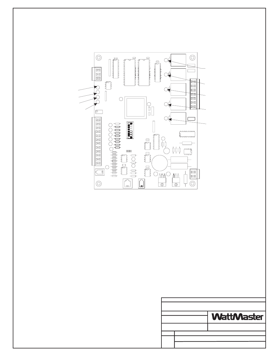
CV-C Controller LED Descriptions
POWER - LED
COMMUNICATIONS - LED
NOT USED
DIAGNOSTIC BLINK CODE - LED
RELAY #1 ENERGIZED - LED
RELAY #2 ENERGIZED - LED
RELAY #3 ENERGIZED - LED
RELAY #4 ENERGIZED - LED
RELAY #5 ENERGIZED - LED
The CV-C Controller uses an on board LED to indicate various diagnostic conditions
during powerup and operation. The CV-C Controller LED is labeled ""COM". Starting
with power up the LED blink codes are as follows:
Off for five seconds
SCAN LED blinks the board address (Address 14 = 14 blinks)
Five second pause
Twenty second time delay - LED blinks twenty times
Status code is repeatedly blinked every ten seconds to indicate controller status:
Priority
No. of Blinks
Status
Lowest
1
Normal Operation
-
2
Override Active
-
3
Bad Zone or Airflow Sensor
-
4
(Not used on CV Units)
Highest
5
Communication Failure
Only the highest priority failure code will be shown. You must correct the highest priority
alarm before other problems will be indicated.