Time delay selection – Basler Electric BE1-81O/U User Manual
Page 16
10
9137300990 Rev N
Selector Switch setting is reached, the logic energizes the setpoint output relay. The total time delay, with
seconds-type timing selected, is the Time Delay Selector Switch setting plus one cycle of the sensed
input plus 0.008 seconds (output relay delay). The Pickup LED remains lit until the frequency condition is
corrected. When the sensed frequency returns to normal for three cycles, the Pickup LED and output
relay reset.
When delay is set in cycles, the relay calculates delay using a zero-cross counter. Hence, the measured
delay will vary with incoming frequency. The time delay may be calculated as follows.
𝑑𝑒𝑙𝑎𝑦 (𝑠𝑒𝑐𝑜𝑛𝑑𝑠 =
𝑑𝑒𝑙𝑎𝑦 𝑠𝑒𝑡𝑡𝑖𝑛𝑔 𝑖𝑛 𝑐𝑦𝑐𝑙𝑒𝑠
𝑎𝑝𝑝𝑙𝑖𝑒𝑑 𝑓𝑟𝑒𝑞𝑢𝑒𝑛𝑐𝑦 𝑖𝑛 ℎ𝑒𝑟𝑡𝑧
× (± 𝑠𝑝𝑒𝑐𝑖𝑓𝑖𝑐𝑎𝑡𝑖𝑜𝑛 𝑎𝑐𝑐𝑢𝑟𝑎𝑐𝑦)
If 00, 01, or 02 is set as the time delay, the relay response will vary according to the revision level of the
relay. The revision-dependent response of the relay may include a block of relay tripping, a trip as fast as
two cycles, or a trip in three or more cycles.
Note
A delay setting of 00, 01, or 02 cycles should not be used unless the
relay response to the setting is tested and found acceptable.
When delay is set in seconds, the relay calculates delay using an internal clock. This gives a time delay
that will not change as the sensed frequency changes.
Time Delay Selection
Time delay selection is controlled by Selector Switch S7 on the definite time circuit board. S7 is a user-
settable, three-section switch for selecting definite timing in seconds or cycles and a multiplier of times 1,
10, or 100.
Note
Earlier BE1-81O/U relays with timing option E1 had a timing range of 3
to 99 cycles and did not include Selector Switch S7. Earlier relays with
timing option E2 had a timing range of 3 to 99 cycles.
To provide rearward compatibility for users of earlier BE1-81O/U
relays with timing option E1, relays are delivered with S7 set to
emulate the E1 timing range.
Sections S7-1 and S7-2 configure the multiplier used with the Time Delay Selector Switches. For a times
one (X1) multiplier, S7-1 and S7-2 are placed in the down position. For a times 10 (X10) multiplier, S7-1 is
placed in the up position and S7-2 is placed in the down position. A times 10 multiplier is also obtained
when S7-1 is placed in the down position and S7-2 is placed in the up position. For a times 100 (X100)
multiplier, S7-1 and S7-2 are placed in the up position.
Section S7-3 either selects cycles or seconds as the unit of measure for the definite time delay. S7-3 is
placed in the up position to select cycles. The down position of S7-3 selects seconds.
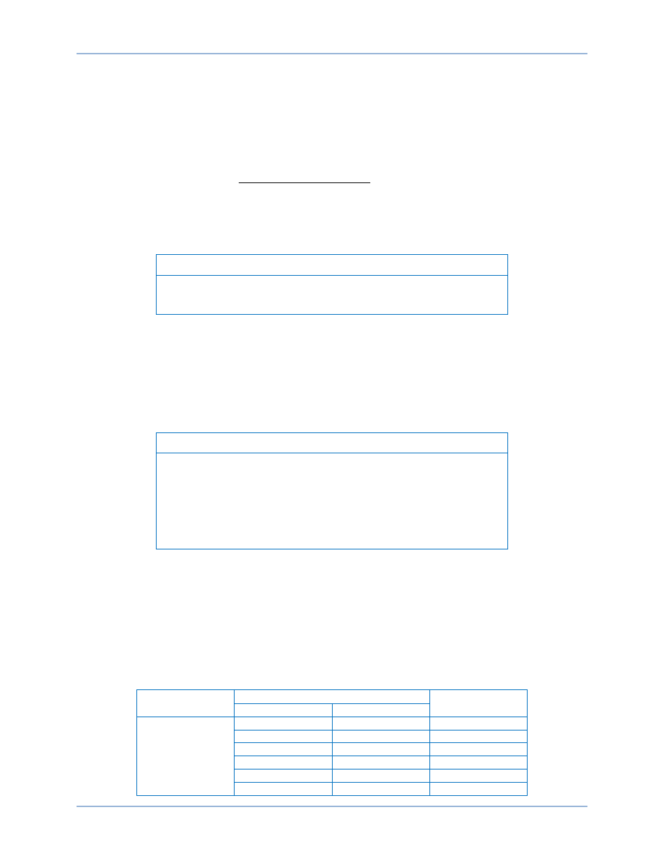
Table 2 lists some time delay setting examples.
Table 2. Time Delay Setting Examples
Time Delay
Selector Switch
Selector Switch S7
Time Delay
S7-1, 2
S7-3
25
X1
Cycles
25 cycles
X10
Cycles
250 cycles
X100
Cycles
2,500 cycles
X1
Seconds
2.5 seconds
X10
Seconds
25 seconds
X100
Seconds
250 seconds
Functional Description
BE1-81O/U