Basler Electric DGC-2020 User Manual
Page 342
utility. Paralleled to utility status is indicated to the DGC-2020 by the parallel to mains
(ParToMains) logic element in BESTlogicPlus Programmable Logic. As an example,
assume that the Ramp Rate is set at 10% per second. If the demand is 50% of the
machine’s capacity, and the generator breaker is closed to parallel the generator to
the utility, it will take 5 seconds for the output to come up to the required level. If the
demand is 80 percent, it will take 8 seconds to come up, etc. This is also the rate at
which the machine will ramp down when going off line in a normal machine stop.
xvi. Base Load Level (%) - When the kW controller is active, this setting defines the level
of the machines rated kW capacity that the DGC-2020 will regulate when the
generator is paralleled to the utility as indicated by the parallel to mains
(ParToMains) logic element in BESTlogicPlus Programmable Logic.
xvii. Base Load Level Source - The set point for the kW controller (when enabled) can
either be the level set in the Base Load Level (%) setting, or it can be derived from
an analog input on the LSM-2020 or AEM-2020 (Analog Expansion Module). Set this
to User Setting or to an available analog input on the LSM-2020 or AEM-2020 as
required for machine implementation.
xviii. Base Load Analog Max (%) - This setting defines the value of kW indicated when the
Base Load Level Source is set to an analog input and the input is at its maximum.
This parameter cannot be configured when Base Load Level Source is set for User
Setting.
xix. Base Load Analog Min (%) - This setting is the value of kW indicated when the Base
Load Level Source is set to an analog input and the input is at its minimum.
xx. Breaker Open Setpoint (%) - This setting specifies the maximum kW level at which
the DGC-2020 will open the generator breaker after unloading prior to stopping the
machine on a normal machine stop in AUTO mode.
f.
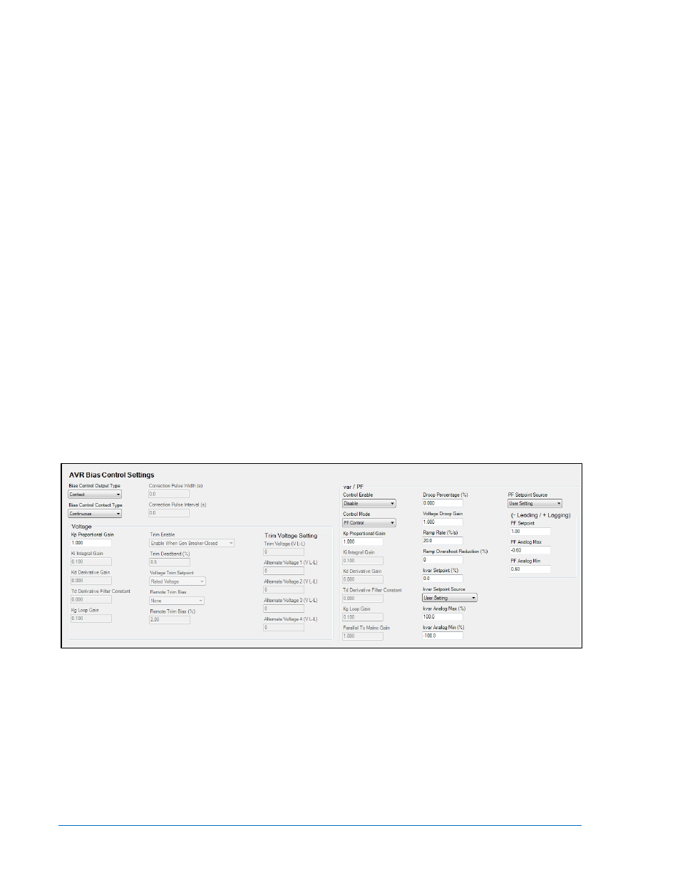
Configure the voltage and kvar control parameters.
The settings for the voltage and kvar control parameters are found in BESTCOMSPlus
®
under SETTINGS EXPLORER > DGC-2020 > BIAS CONTROL SETTINGS > AVR BIAS
CONTROL SETTINGS. See Figure 7-60.
Front Panel Navigation Path: SETTINGS > BIAS CONTROL > AVR BIAS CONTROL
Figure 7-60. Settings Explorer, Bias Control Settings, AVR Bias Control Settings Screen
i. Bias Control Output Type - Select Contact or Analog, according to the machine’s
implementation.
ii. Bias Control Contact Type - Select Continuous or Proportional, depending on the
contact output type. Proportional is a PWM based implementation. The duty cycle
increases when more control output is required. This parameter cannot be
programmed if the Bias Control Output Type is set to Analog since it is not applicable
to analog outputs.
iii. Correction Pulse Interval - This setting defines the duration in seconds between
output pulses for proportional contact outputs. This is the inverse of the frequency of
the pulses. This parameter cannot be programmed if the Bias Control Output Type is
7-54
DGC-2020 Setup
9400200990 Rev X