Generator network status display, Mains fail transfer status display, Generator network status display -26 – Basler Electric DGC-2020 User Manual
Page 66: Figure 2-5. breaker hardware one-line diagram -26
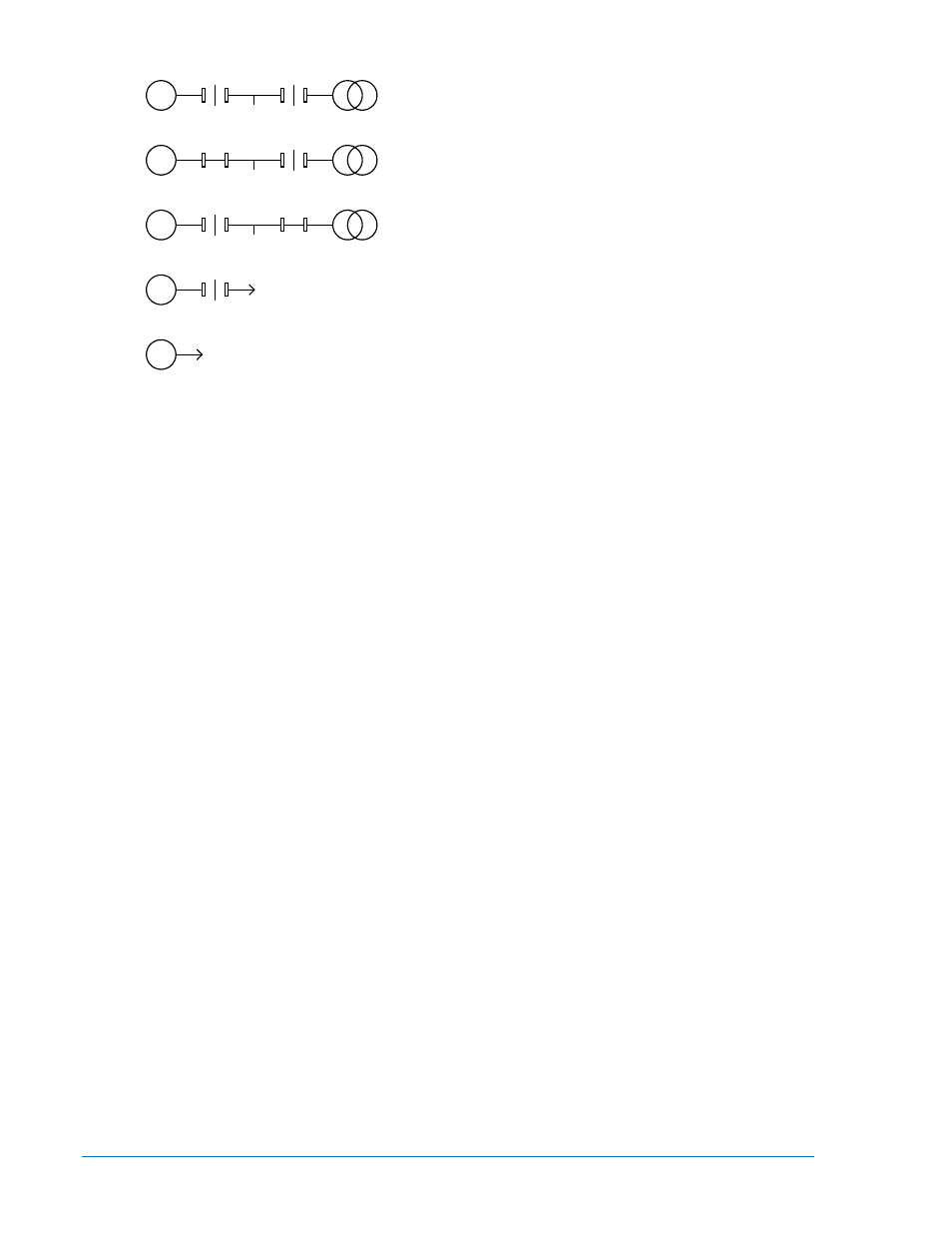
Generator and mains breakers are configured and
both breakers are open.
Generator and mains breakers are configured. The
generator breaker is closed and the mains breaker
is open.
Generator and mains breakers are configured. The
generator breaker is open and the mains breaker is
closed.
Generator breaker is configured and open.
No breakers are configured.
Figure 2-5. Breaker Hardware One-Line Diagram
Generator Network Status Display
The status of the generator network is available on the front panel of each DGC-2020 when the generator
is part of a multi-machine network. The System Type setting (found under Settings > System Parameters
> System Settings) configures the machine to be part of a multi-machine network. When System Type is
set to Multiple Generator, the machine is configured for participation in a multiple machine system.
Generator network status is found on the front panel under Metering > Alarms-Status > Network Status.
•
System Manager - the sequencing ID of the machine that controls all dead bus arbitration and
generator sequencing. This ID is always assigned to the machine on the network that has the
lowest nonzero value of sequencing ID.
•
Number of Units - the number of units on the generator network. The sequencing IDs of all
machines on the network are listed as ID1:, ID2:, etc.
All machines on the network display the same value for System Manager and Number of Units. Each unit
to be used as part of generator sequencing or dead bus breaker arbitration must have a unique nonzero
sequencing ID. The ID Missing and ID Repeat pre-alarms annunciate when a machine is not configured
for proper system operation.
The System Manager and Number of Units parameters display zero when the DGC-2020 is not
communicating with an LSM-2020. The System Manager parameter displays
−1 when a system manager
is not present on the network (all unit IDs are zero).
Mains Fail Transfer Status Display
Mains Fail Transfer Status can be viewed in three locations, however, Mains Fail Transfer must first be
enabled.
To enable Mains Fail Transfer, navigate to Settings > Breaker Management > Breaker Hardware > Mains
Fail Transfer using the front panel controls or Settings Explorer, Breaker Management, Mains Fail using
BESTCOMSPlus.
Mains Fail Transfer Status is displayed on the front panel in Metering > Alarms-Status > Mains Fail
Transfer and also on the Breaker Hardware One-Line Diagram screen. It is displayed in BESTCOMSPlus
on the Metering Explorer, Mains Fail Transfer Status screen.
These screens display the Mains Fail Transfer State and any timers relevant to the mains fail transfer
process. These parameters are listed below.
Mains Fail Transfer State: The different mains fail transfer states are described below.
Power From Mains: Power is being supplied to the load from the mains bus.
Transfer Timer Active: Transfer Delay timer is actively counting.
Transferring to Gens: Load is being transferred to the generator bus.
Power From Gens: Power is being supplied to the load from the generator bus.
Return Timer Active: Return Delay timer is actively counting.
G
L
G
L
G
L
G
L
G
L
P0071-88
2-26
DGC-2020 Human-Machine Interface
9400200990 Rev X