Signal connector, Power connector, Ecm motor connections – Boyertown Regal Oil Fired Furnace Variable Speed 2 Stage ECM Motor User Manual
Page 11: Venting
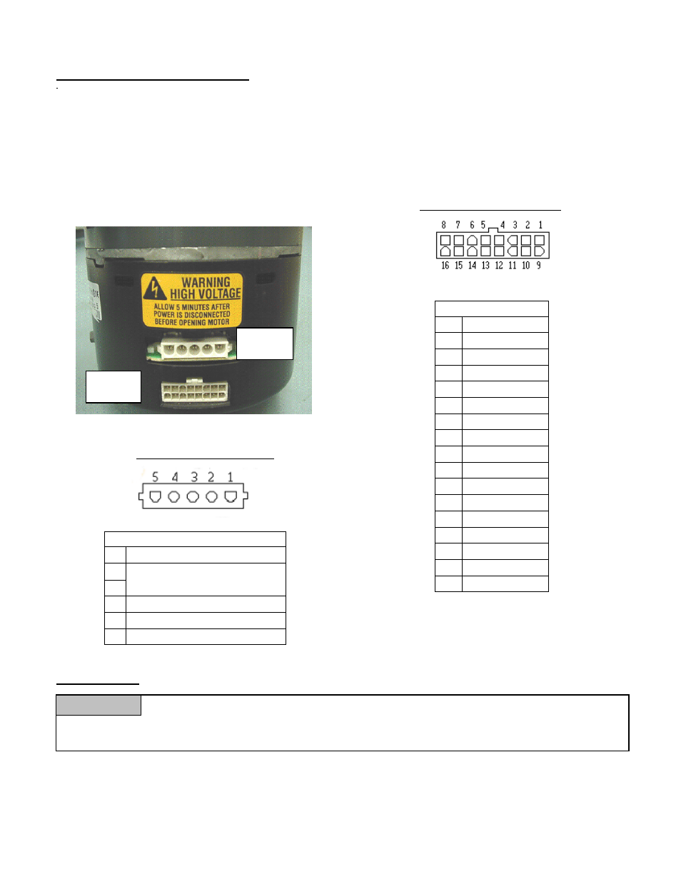
ECM Motor Connections
\
The operation of the motor requires two main connections: the power input connector which is 120VAC,
and the signal input connector from a 24VAC thermostat. Figure 1 shows the location of the connectors
on the motor. When wiring your ECM 2.3, the pin locations are crucial in assuring that no damage is done
to the motor or the control. Figures 2 and 3 show the pin locations for both connectors, when viewing the
motor as shown in Figure 1
Figure
2
Signal
Connector
Signal Connector
Pin
Description
1 C1
2 W/W1
3 C2
4 DELAY
5 COOL
6 Y1
7 ADJUST
8 OUT-
9 O
10 BK/PWM
11 HEAT
12 R
13 EM/W2
14 Y/Y2
15 G
16 OUT+
Power
connector
Signal
connector
Figure 1
Figure 3Power Connector
VENTING
Failure to follow all instructions can result in flue gas spillage and carbon monoxide
emissions, causing severe personal injury or death. All chimneys must meet the requirements of
NFPA 211 and NFPA 31.
Power Connector
Pin Description
1 JUMPER PIN 1 TO PIN 2
2 120 VAC LINE INPUT
3 CHASSIS
GROUND
4 AC
LINE
5 AC
LINE
WARNING
Note: For ease of installation the thermostat wiring may be attached to the air flow switch plate before
attaching vent piping the furnace flue outlet.
Chimney
The furnace must be connected to an adequate chimney or an approved venting system in accordance
11