Burner installation – Boyertown Regal Oil Fired Furnace Variable Speed 2 Stage ECM Motor User Manual
Page 15
outdoors or from spaces freely communicating with the outdoors. In this situation, permanent
openings having a total free opening area of not less than 1 square inch per 5000Btu/Hr of total input
of all appliances must be provided.
If the furnace is located in a confined space (A space whose volume is less than 50 cubic feet per
1000Btu/Hr of the combined input ratings of all appliances installed in that space) the confined space
shall have two permanent openings, one 6 inches from the top of the space and one 6 inches from the
bottom of the space. Each opening shall have a free area opening of not less than 1 square inch per
1000Btu/Hr of total input rating of all appliances in the enclosure freely communicating with interior
areas having adequate infiltration with the outside.
If adequate infiltration air is not available the confined space shall be fitted with two openings, one 6
inches from the top of the enclosure and one 6 inches from the bottom of the enclosure. Each opening
shall have a free area of at least 1 square inch per 2000Btu/Hr of the total input of the appliances in
the enclosure.
In calculating free area, consideration must be given to the blocking effect of louvers, screens or grills
protesting the opening. Screens used shall not be less than ¼” mesh and shall be readily accessible for
cleaning.
Burner Installation
Remove the oil burner from its shipping carton and inspect thoroughly. Verify that the
correct burner combination and nozzle is installed in the burner as shipped.
Read the oil burner manual included in the shipping carton and follow the instructions for preparing
and installing the burner. Refer to Table 9, Table 10, or Table 11 for the burner specifications for
your unit.
On units which can be multi fired, a nozzle change may be required. Follow the oil burner manuals
instructions for the proper installation of the nozzle.
Verify that the electrode settings match the manufacturers recommended settings.
Inspect the combustion chamber. Verify that it is in the correct position in the heat exchanger and is
in good condition.
The oil burner is to be bolted to the pouch plate using the burner mounting flange gasket and the nuts
supplied. Make sure that the burner passes through the burner opening in the combustion chamber and
does not protrude into the combustion chamber. Refer to the wiring section of this manual for the
correct wiring connections to the furnace and to the oil burner manual for fuel piping.
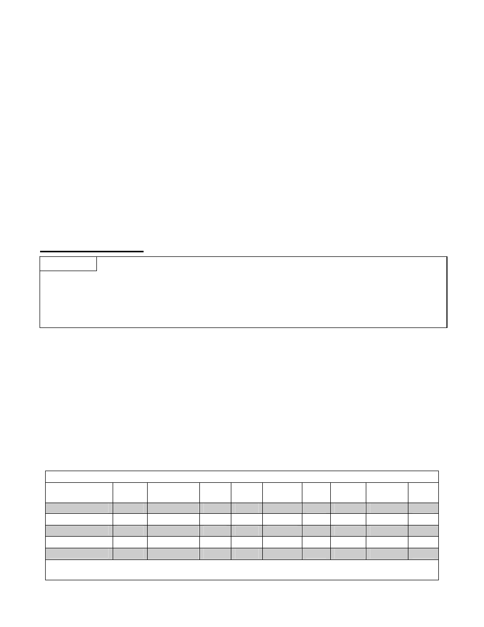
Table 9 Beckett Burner Specifications
Furnace Model
Burner
Model
Delavan
Nozzle
Pump
Press.
Air
Band
1
Air
Shutter
1
Head Tube
Length
Insertion Static
Plate
LB/HB 600
AFG
0.60X80
º
A
100
0
4
F-3
2
6-1/2”
5-1/2”
3-3/8
LB/HB 750
AFG 0.75X80
º
B 100 0
6 F-3
2
6-1/2” 5-1/2” 3-3/8
LB/HB 850
AFG
0.85X80
º
B
100
0
9
F-3
2
6-1/2”
5-1/2”
3-3/8
LB/HB 1000
AFG 1.00X80
º
B 100 0
5 F-6
2
9” 7-3/4”
3-3/8
LB/HB 1250
AFG
1.25X80
º
B
100
0
8.5
F-6
2
9”
7-3/4”
3-3/8
Notes: 1. Approximate air settings, see start up procedures for final adjustments.
2. With ceramic amulet and Stainless Air Tube. 3. Low Firing Rate Baffle installed.
NOTICE
15