BUG-O Systems CWP-5 User Manual
Page 20
20
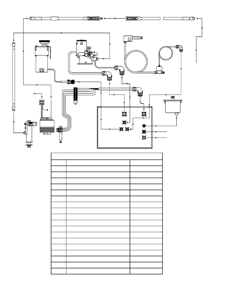
CWP-5 CIRCLE WELDER / WIRING DIAGRAM
ELECTRICAL COMPONENT CHART
ITEM DESCRIPTION
PART NO.
1
Weld Cable Inlet 2/0
CWO-3020-2/0
2
Weld Cable
CWO-3013
3
Weld Cable 50’
CWO-3019
4
Large Brush Holder & Support
CWO-3059
5
Power Cable
CWO-3139*
6
GMA Pigtail
CWO-3331
7
Dual Control Box
CWP-1570
8
P.M. Motor Assembly
CWO-3384
9
CWP-5 Collector
CWO-3456
10
Small Brush Retainer Assembly
CWO-3462
11
LN-7 Wire Feeder Assembly
CWO-3468
12
Terminal Block
CWO-3935
13
Rotation Encoder Assembly
CBP-1595-5
14
Solenoid Adapter Kit
CWO-8056
15
Shunt Bar
CWO-6008
16
CWP-5 Shunt Cable
CWP-1585
17
Cable 18"
MUG-1621-1.5
18
Shielded Cable
MUG-1634-3
*CWO-3139 Universal CWO-3139-M for Miller Welders
1
3
8
2
11
14
6
12
TO
POWER
CABLE
5
4
9
10
IN FROM
WELDER
SUPPLY
UNIT
7
WHT
BLK
RED
ORG
GRN
WHT
BLK
RED
ORG
13
15,16
IN FROM Y-DRIVE
IN FROM VACUUM
17
18