Setup and operation, cont’d – BUG-O Systems CWP-5 User Manual
Page 7
7
MAKING A WELD
1. Connect the ground cable to the workpiece. The ground cable must make good electrical contact with
the work.
2. Set Weld ON/OFF Switch to the OFF position.
3. Depress red STOP button.
4. Position the welding gun at the start position using the Racking System CBP-1670 and the rotation
controls. Position the electrode in the joint. The end of the electrode may be lightly touching the work.
5. Depress the black RESET button to set a new Home position.
6. Using the keypad, call up the desired program number or input a new program. When finished, press
“D” to review the program data.
7. Set the Weld ON/OFF Switch to the ON position.
8. Depress the green START button to begin the weld program.
9. Turn on the FLUX RECOVERY VACUUM Switch to the ON position.
10. The CWP-5 will automatically stop at the end of the weld program.
WARNING: When using an open arc process, it is necessary
to use correct eye, head and body protection.
SETUP AND OPERATION, CONT’D.
MACHINE CONTROLS
Please refer to pages 8-9 in this manual entitled CWP-1570 Control Panel for descriptions of the various
control parameters that are available.
WELD STARTING POSITION
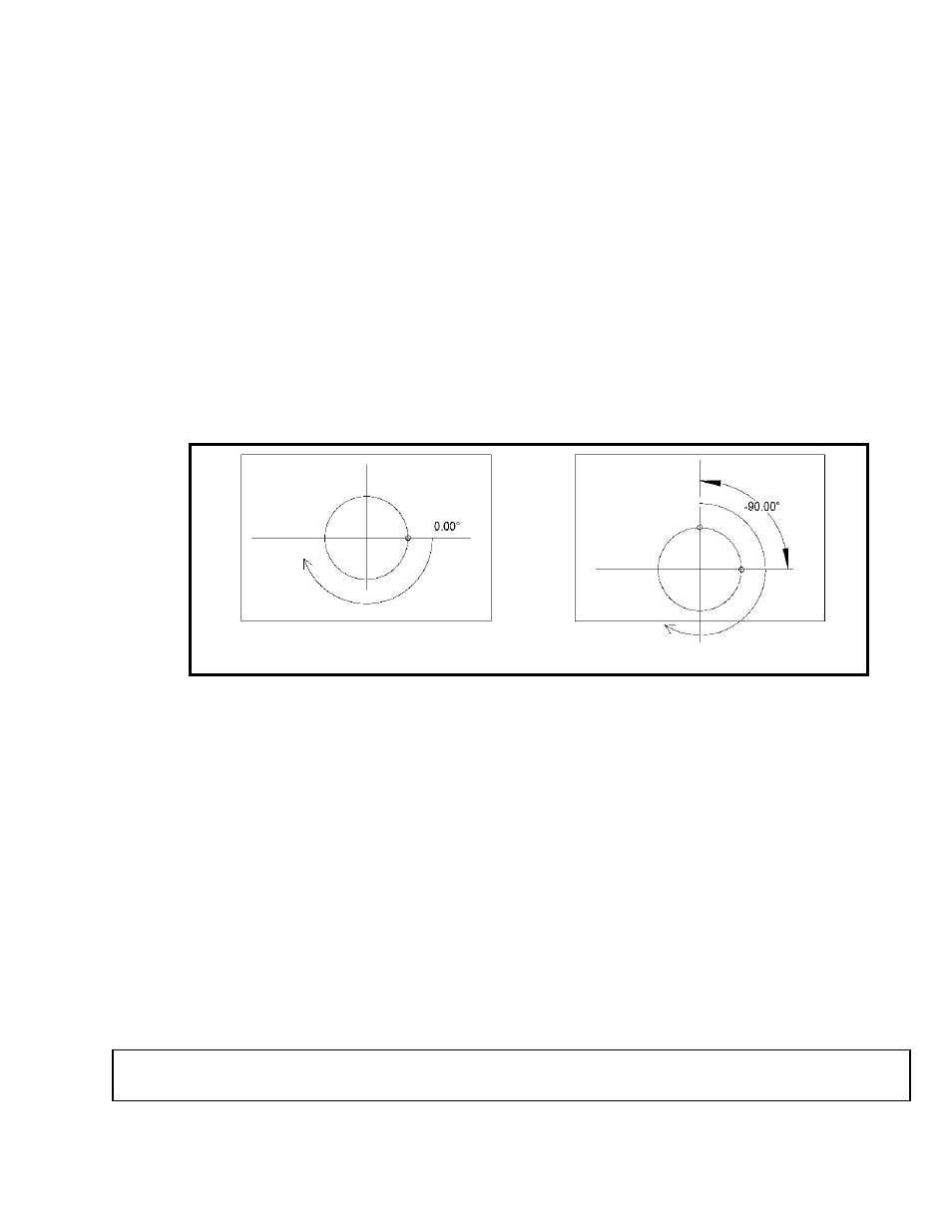
Proper positioning of the electrode is crucial to a successful weld. The CWP-5 rotates in a clockwise
direction. Depending on the job, whether on-center or hillside, or the process, the optimum starting point
of the weld may vary. The desired starting position should be entered at setup as an angle to the pipe
axis direction, as shown in Figure 3.
The default start position (start angle = 0.00°) is shown as A and B in Figure 3. For an on-center joint, this
would be the topmost point. For a hillside joint, -90.00° is the topmost point (C in Figure 3) and 90.00° is
the lowest point.
During setup, enter the Start Angle in hundredths of degrees: 4500 is 45.00°. The machine makes one
revolution from the start point for each pass. Overlap is only added to the last pass.
Figure 3: Weld Start Position for On-center (left) and Offset or Hillside (right) nozzles.
C
B
A