BUG-O Systems CWE-5 User Manual
Page 10
10
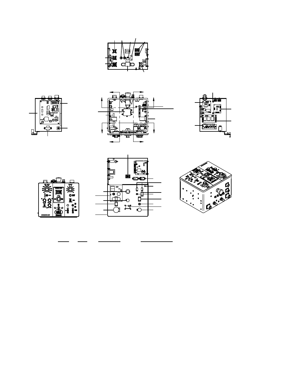
CWE-1000-B CW-5 CONTROL BOX / PARTS DIAGRAM / PARTS LIST
SECTION A-A
SECTION B-B
SECTION C-C
SECTION D-D
A
A
B
B
C
C
D
D
62
22,30,38,70
40
41
42
43
44
45
20
21
37
55
56
63
9
25
28
66
25
28
51
66
25
28
50
66
17
27
30
69
70
24
31
71 29
33
61
68
20
58
63
19
22
30
70
13
21
29
67
4
26
28
48
66
10
11
12
53
32
49
54
1
31
64
15
18
11,36
3,11
52
46
6
20
59
20
57
63
35
29,60,68,72
16
62
14,25,28,66
2,5,7,8,23
34 39
29
60
68
72
65 47
ITEM
QTY
PART NO.
DESCRIPTION
1
2
ABP-1069
Toggle Switch
2
2
ARV-1113
1/ NPT 90 Degree Street Elbow
3
1
BUG-1562
Muti-Turn Potentiometer
4
1
BUG-1764
Meter Display Board Assembly
5
2
BUG-2062
Male Thread Protector
6
1
BUG-2255
Toggle Switch
7
1
BUG-3155
Adaptor Kit
8
2
BUG-9096
Outlet Bushing, Oxygen
9
1
BUG-9486
Panel Connector, 2T, M
10
1
BUG-9677
Potentiometer
11
3
BUG-9687
Knob, Fluted Phenolic w/ Skirt
12
1
BUG-9694
Knob
13
2
CBP-2006
Relay DPDT 10A 110/220VAC
14
1
CON WTE 0383
Panel Connector, 5T, M
15
1
CWE-1005-A
Face Plate
16
1
CWO-6089
Ctrl. Enclosure Remote
17
1
CWO-6335
RFI Filter
18
1
CWO-6527
DPDT On-None-On Toggle