Setup and operation, cont’d – BUG-O Systems CWE-5 User Manual
Page 6
6
SETUP AND OPERATION, CONT’D.
ADDITIONAL CABLES
The circle welders are supplied with the following cables:
1. CWO-3139 50' (15 m) power cable that connects the power source to the cable connector on the top gear
of the machine.
2. CWO-3019 50' (15 m) weld cable that connects the lead coming out of the top of the machine using the
quick connect connector to your power supply.
3. CWO-9406 50' (15 m) gas shielding hose that connects the gas fitting on the top of the shaft to your
shielding gas supply.
WIRE SPEED AND VOLTAGE ADJUSTMENT
The wire speed control on the front of the CWE-1000-B Control Box
has a dial that is calibrated directly in inches per minute. Set the
voltage using the control on the power source.
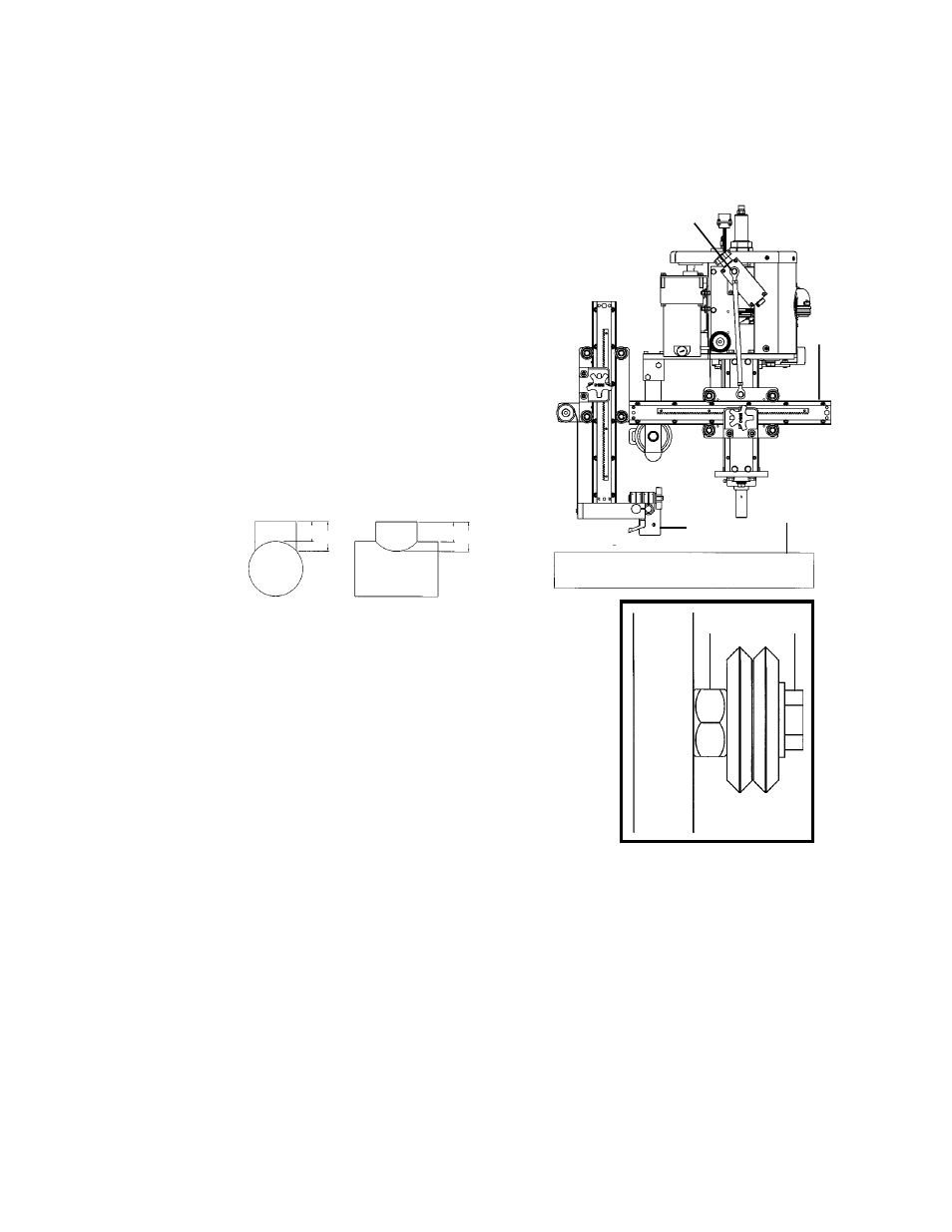
RISE AND FALL OF THE CAM
All circle welders are equipped with a rise and fall cam assembly. The
cam assembly must be aligned before any other settings can be made.
To align the cam rotate the machine so the horizontal rack is parallel
to the pipe, then adjust the gun holder so it is perpendicular to the
horizontal rack. Position torch tip to top dead center of joint. Loosen
the set screws in the brass block on the cam, and rotate the cam to the
vertical position as shown. Refasten set screws.
WHEEL ADJUSTMENT
The CWE-5 Racking System CWO-1670 and the Small Vertical Racker CWO-
1685 are equipped with adjustable wheels. Always check these components for
proper wheel adjustment before using the machine. The wheels need adjustment
if you can cock or wiggle the components out of alignment. The wheels should be
snug but not prohibit movement along the path of travel. The wheels with the hex
stand offs are adjustable. To adjust the wheels, loosen the hex bolt
(A) until the
adjustable bushing
(B) can be rotated. Correct the wheel alignment by rotating
the adjustable bushing
(B). Once adjusted, hold the adjustable bushing (B) while
tightening the hex bolt
(A). Recheck alignment.
MACHINE CONTROLS
Operational parameters can be set using the CWE-1000-B Control Box. Please
refer to the sections in this manual entitled CWE-1000-B Programmable Rotation
Controls for descriptions of the various welding parameters that are available, as
well as for descriptions of the various speed and directional capabilities.
CAM SETTING
The cam setting is equal to distance “B” subtracted from distance “A”.
Example:
Let A=3 and B=2
3-2=1
The cam setting is 1.
MAKING A WELD
1. Position the gun to start position using the CWO-1670 CWE-5 Racking System.
2. Connect the ground cable to the workpiece. The ground cable must make good electrical contact with
the work.
3. Select Automatic Mode
4. Position wire
5. Cycle start
6. Machine stops and reverses to start position
A
B
WARNING: When using an open arc process, it is necessary
to use correct eye, head and body protection.
Horizontal Rack
Cam
Torch Holder
Pipe
B A
B A