Installing the bug-5960 drive carriage – BUG-O Systems BUG-6550 User Manual
Page 28
28
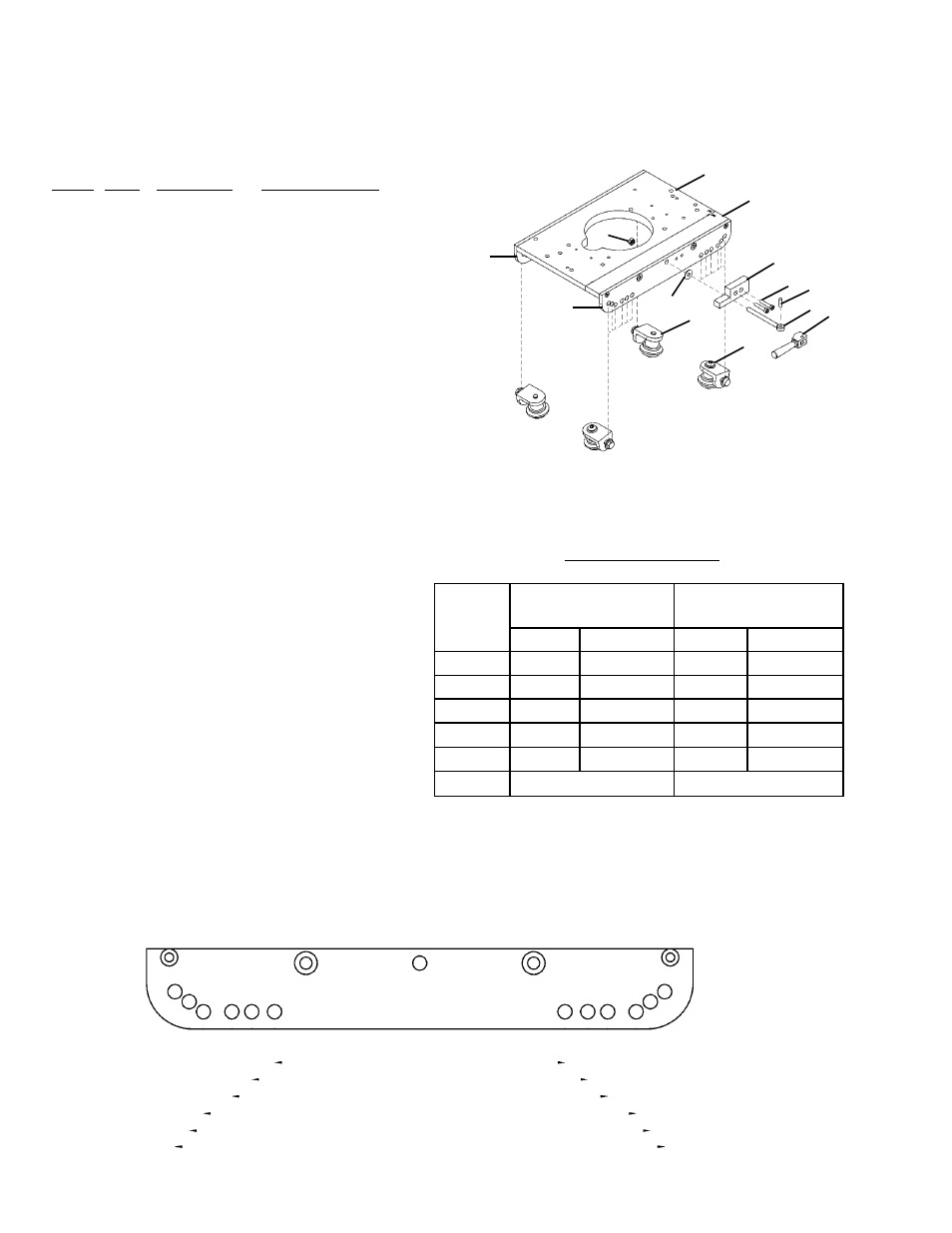
BUG-5960 TUBE CARRIAGE / EXPLODED VIEW / PARTS LIST
The Tube Carriage features a split carriage body for quick and easy placement on the rail. It has a carrying
capacity of 100 lb (45 kg). The carriage also offers six (6) wheel positions for circumferential applications
over a wide range of diameters. Use with BUG-O Aluminum Rigid, Semi-Flex or Bent Rigid Rails.
ITEM QTY PART NO
DESCRIPTION
1
1
BUG-5908A Plate Assembly (Incl. Spring x2
& Dowel Pin x2, not shown)
2
1
BUG-5907 Skirt, Right
3
1
BUG-5964 Skirt, Left
4
2
BUG-5918 Fixed Wheel Assembly
5
2
BUG-5920 Adj. Wheel Assembly
6
1
BUG-5961 Modified Cam Handle
7
1
BUG-5962 Cam Stop Block
8
1
BUG-5963 Swing Eye Bolt
9
1
BUG-5916 Dowel Pin
10
1
ARM-2316 Thrust Race
11
1
FAS-1353
Hex Nut, 1/4-20
12
2
FAS-0537
Screw, Soc Hd Cap 10-24 x 3/4
INSTALLING THE BUG-5960 DRIVE CARRIAGE
1. Select the correct pair of holes on each side of the carriage for the rail diameter being used (see chart).
If the wheels are not attached to the correct set of holes, remove them and bolt the wheel brackets
in selected holes. Tighten the bolts until the brackets are snug, but still free to rotate.
2. Open the cam handle to separate the carriage.
On the drive unit, loosen and turn the clutch
knob counterclockwise to declutch the drive
pinion.
3. Place the carriage on the rail with the wheels
in the rail grooves. Close the cam handle
and move the carriage back and forth a
few inches. The wheels on their mounting
brackets will align themselves correctly in the
rail grooves.
4. Verify that wheels are properly aligned, then
tighten the wheel mounting bolts to lock them
in position. Rotate the clutch knob clockwise
to engage the drive pinion with the rack.
5. Verify that pinion is properly engaged in the rack. The correct wheel position will provide a minimum
of 1/8" engagement (approx. 3 mm) between the drive pinion and the gear rack.
Note: For some rail
or pipe sizes, the pinion height may need to be adjusted.
2
1
11
3
1
6
8
9
12
7
4
5
10
F
E
D
C
B
A
Carriage
Wheel
Hole Set
BRR-1210
Rail ID
Pipe OD
in
mm
in
mm
A
20 - 25
500 - 635
9 - 21
230 - 530
B
23 - 35
585 - 890
12 - 31
300 - 790
C
30 - 44 760 - 1120
18 - 40
455 - 1015
D
41 - 60 1040 - 1525 29 - 54
735 - 1375
E
75 - 174 1905 - 4420 64 - 170 1625 - 4320
F
flat rail
flat rail
Note: Chart values are for reference only