BUG-O Systems BUG-6550 User Manual
Page 31
31
SERVICE PROCEDURE: INSTALLING THE CROSS ARM (WPD-1150)
OPTION 2 - The Electrical Way
Tools required: Ohm meter rated to at least 5k Ohm, flat screw driver, 3/32" hex key, tape measure or other
measuring device.
1. Place machine on blocks to protect the drive pinion (underneath).
2. Remove Right Side Panel (BUG-5708) from the clutch side of the Drive Unit (BUG-5980).
3. If necessary, install the Cross Arm (WPD-1150). Insert from the brass gear side. Make sure the brass
gear teeth and the V-guide teeth do not skip.
4. Center the cross arm. The V-guide will stick out of the machine by 4.25 in (110 mm) on each side when
centered.
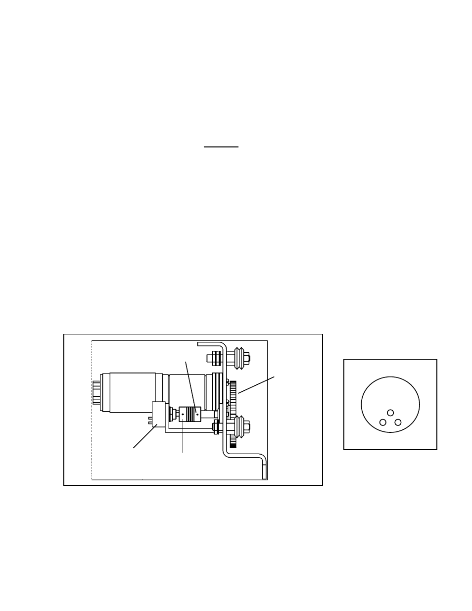
5. Loosen only the set screw on the gear side of the coupling between the brass encoder gear and the
potentiometer. Refer to Figure 8.
6. Unplug wire harness leading from Potentiometer.
7. Using an Ohmmeter, measure resistance across Node 1 and Node 3 (refer to Figure 9). This should
measure approximately 5000 ohms.
8. Rotate the Potentiometer until resistance across Node 1 and Node 2 is equal to resistance across
Node 2 and Node 3, approximately 2500 ohms. The Potentiometer is now centered.
9. While being careful not to move the Potentiometer, secure the coupling to the gear shaft.
10. Plug wire harness from Potentiometer into proper terminal on the speed control board (CAS-1770).
11. Connect to power supply of appropriate voltage, turn machine ON and verify that Cross Arm is centered.
12. Install Right Side Panel.
13. If necessary, install Arm Stop (WPD-1164) and Height Slide Assembly (CAS-1500) to the end of the
Cross Arm.
Figure 8: Simplified side view of machine with right cover
(BUG-5708) removed.
1
3
2
Figure 9:
Potentiometer nodes
used in Steps 7 & 8.
Brass
(Encoder)
Gear
Potentiometer Coupling
Set screw
to loosen