Service procedure: installing the cross arm – BUG-O Systems BUG-6550 User Manual
Page 30
30
SERVICE PROCEDURE: INSTALLING THE CROSS ARM (WPD-1150)
OPTION 1 - In the Field
NOTE: Read and understand whole procedure before attempting.
Tools required - flash light or well lighted area, marking pen, tape measure or other measuring device.
1. Place machine on blocks to protect the drive pinion (underneath).
2. Turn machine OFF and disconnect from power supply.
3. Remove the Arm Stop (WPD-1164) and the Height Slide
Assembly (CAS-1500).
4. Remove the existing Cross Arm (WPD-1150). Manually push/
pull the Cross Arm from the machine
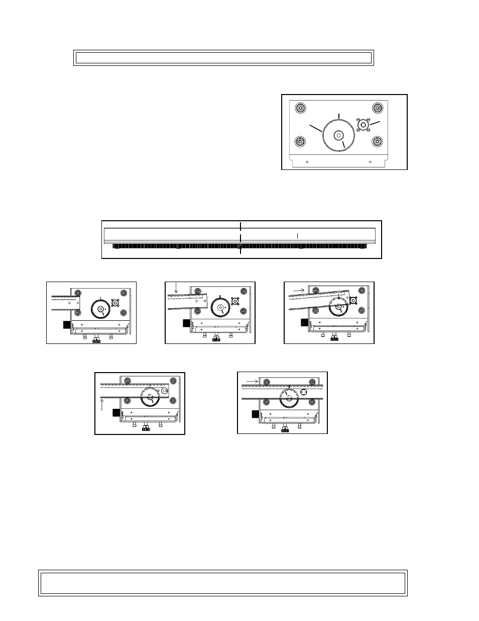
5. Looking from the clutch side of the drive unit, locate the
reference mark on the mounting plate (“A” in Figure 1) and the
reference mark on the face of the brass encoder gear (“B” in
Figure 1).
6. As shown in Figure 1, position reference “B” at approximately the 5 o’clock position.
7. Make a mark on the cross arm 3 5/8" right of center (“C” in Figure 2). This will serve as a reference
line for centering the cross arm.
8. Inserting from the brass gear side, install the Cross Arm, as shown in figures 3-7.
Be careful not to bump or mesh brass gear and V-guide rack until V-guide is ready to engage pinion
also. Run the Cross Arm until it is centered (align reference mark “C” with face of side plate). Make
sure the brass gear teeth and the V-guide teeth do not skip.
9. If necessary, connect the Pendant Control (BUG-5755) to the Drive Unit (BUG-5980) using the Pendant
Control Cable (BUG-5551-10).
10. On the control pendant, center steering control (1 1/2 turns from either extreme).
11. Connect the machine to a power supply of the proper voltage and turn machine ON to verify that Cross
Arm is centered. The centered V-Guide should stick out of the machine by about 4.25 in (110 mm) on
each side.
12. If satisfied with position of Cross Arm, install Arm Stop and Height Slide Assembly; else repeat steps
4-11.
Note: Reference mark B will no longer apply if the potentiometer was changed in service or
the cross arm was previously centered using the electrical method on page 31.
A
B
A
B
Figure 4: Push down on
arm to tilt V-guide up.
Figure 3: Insert Cross
Arm into guide wheels.
A
B
Figure 6: When arm is ready to
mesh with pinion, push up on arm.
A
B
Figure 7: Push cross arm
in until it is centered.
A
B
Figure 5: Push cross arm into
machine. Avoid brass gear
Figure 1: Proper positioning of reference
marks A and B before the V-guide is inserted.
A
B
Pinion
Encoder
Gear
Figure 2: Placement of reference mark C on the V-guide.
C
CL