Connecting and mounting – cdr-1 – Cloud Electronics CDR-1B User Manual
Page 10
CDR‑1 & CDR‑1F Installation Guide v2.0
10
Connecting and mounting – CDR-1
The CDR-1 is designed for use with single-gang UK, US or Australian electrical back
boxes, using the mounting plate provided. It is also possible to mount it without a back
box directly onto a wall.
The mounting plate has several sets of fixing holes to accommodate the different styles
of box. UK single-gang boxes are square, but note that if fitting to a US or Australian
box, it should be fitted with the long axis horizontal (‘landscape’ orientation), with the
screw holes to left and right.
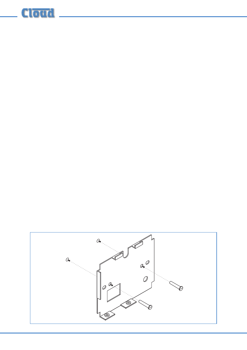
1. Detach the mounting plate from the rear of the CDR-1 by removing the two
countersunk M3 screws. Retain the screws.
2.
With back box: bring the CAT-5 cable(s) into the back box and pass through the
entry hole on the mounting plate. If a local external PSU is being used to power
the CDR-1, the DC feed from this should be fed through as well.
Without back box: simply pass the cables through the mounting plate entry
hole.
3.
With back box: attach the mounting plate to the back box using the M3.5 screws
provided and the appropriate holes in the mounting plate (according to back box
type).
Without back box: fix the mounting plate directly to the wall, using screws (not
supplied) of a length and type appropriate for the wall construction. Note that it
is important that only countersunk-headed screws are used, as a raised screw head
may foul the CDR-1’s internal PCB.