J1 settings – Cloud Electronics CDR-1B User Manual
Page 14
CDR‑1 & CDR‑1F Installation Guide v2.0
14
3. Check that jumper J1 is in the OFF position. J2 should be set according to the
CDR1F’s position in the CAT-5 “chain”. If it is the final (or only) panel in the chain
(i.e., nothing is plugged into the POWER OUT connector), set J2 to END; in all
other cases set it to MID. Carefully use tweezers or a pair of fine-nosed pliers for
this operation.
MID
END
OFF ON
MID
END
OFF ON
J1 Settings
End of chain
Middle of chain
4.
With back box: carefully position the rear metal screening box of the CDR-1F
into the back box, taking care that the CAT-5 cable(s) and PSU wiring (if used) are
not under any strain. Insert the two M3.5 raised-head screws supplied through
the fixing holes in the front plate and engage them in the threaded inserts or lugs
of the back box. Tighten until the panel is neatly flush against the wall – do NOT
over-tighten.
Without back box: carefully position the rear of the unit in the hole, and fix the
front panel with screws of a type and length appropriate to the wall construction.
No. 6 woodscrews are satisfactory provided that timber battens are available
either side of the hole.
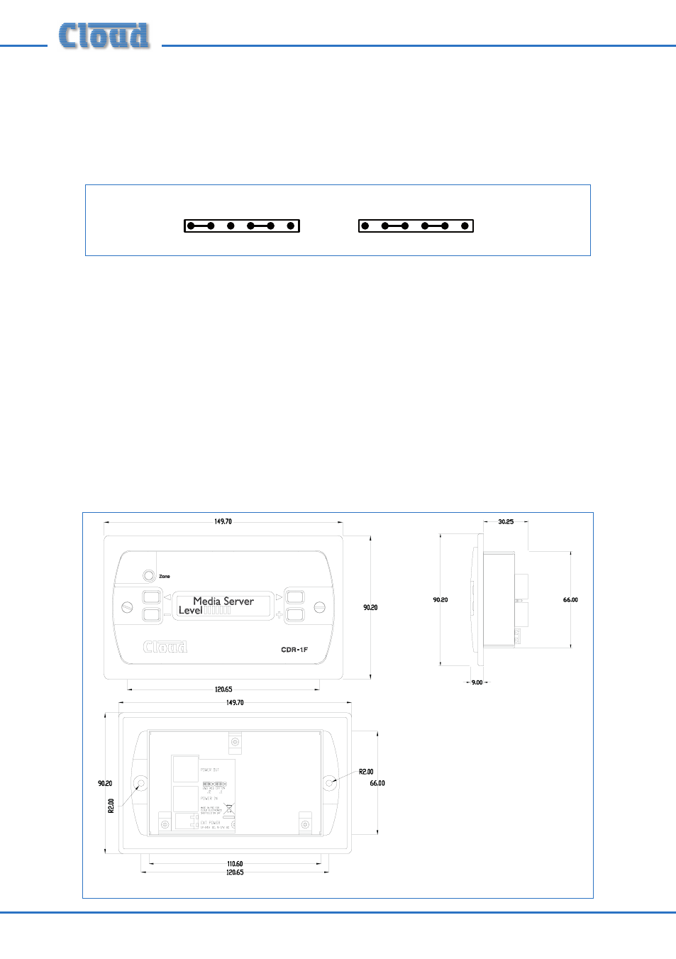
CDR-1F Dimensions