Wiring – Cloud Electronics CDR-1B User Manual
Page 9
Advertising
CDR‑1 & CDR‑1F Installation Guide v2.0
9
Wiring
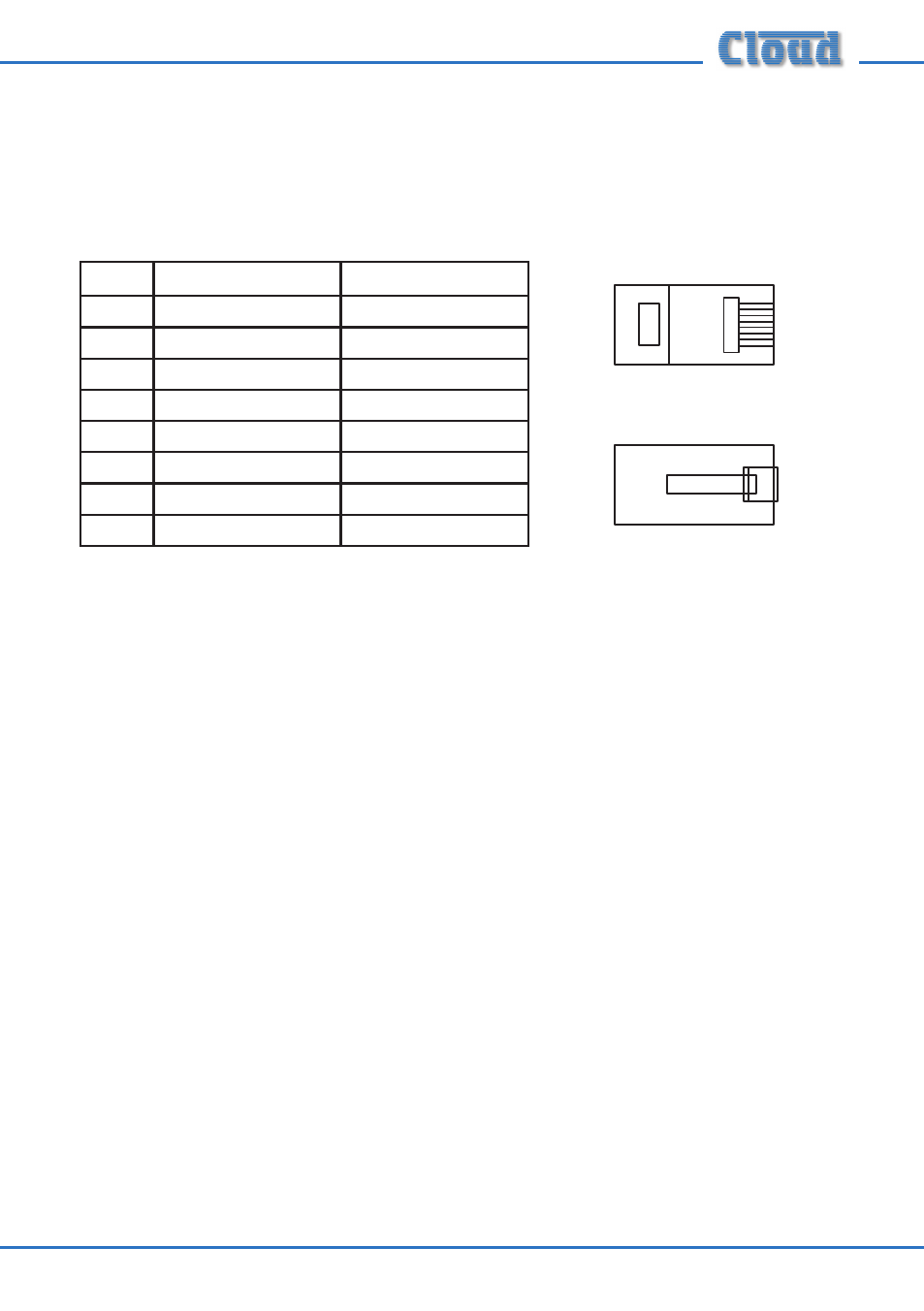
Feed the installed CAT-5 cable(s) (or pre-made patch cable(s)) into the back box
on which the CDR is to be mounted. If not using pre-made cables, crimp the RJ45
connector(s) as per the pinout diagram below:
PIN
USE
CAT-5 CORE
1
n/u
White + Orange
2
n/u
Orange
3
n/u
White + Green
4
DC +ve
Blue
5
0v
White + Blue
6
n/u
Green
7
Data H
White + Brown
8
Data L
Brown
The connection at the DCM-1/e end is identical. Note that the CAT-5 interconnection
provides DC power as well as data, but also see the following chapters concerning
connecting and mounting the CDR-1 and CDR-1F.
1
8
1
8
1
8
1
8
Advertising