3 conventional or trunked channels, 2 transmitter & receiver (tx/rx), 1 transmitter – Codan Radio Transportable Radio Systems User Guide User Manual
Page 16: 2 receiver, 3 transceivers, 4 frequency bands
www.codanradio.com
© Copyright 2015
© Copyright 2015
www.codanradio.com
PAGE 31
PAGE 30
4.1.3 Conventional or Trunked Channels
Depending on the size of deployment planned it may be necessary to support multiple channels. Different trans-
portable packages exist to address different channel capacities. For example, the Codan ET-5 developed for the ATF
(Section 3.3.1) is a single channel repeater. By contrast a base station can support up to 32 channels selectable one at
a time. If there is a requirement for a large number of simultaneous channels to be used then a trunked transportable
system may be required as detailed in Section 3.3.3. More channels mean more cost, size and complexity.
4.2 Transmitter & Receiver (TX/RX)
The transmitter and receiver are the brains of a Transportable Radio system. A repeater, whether it is permanently
installed infrastructure or a Transportable Radio, will always have a distinct transmitter and receiver operating on
their own frequency. Since Transportable Radios are powered by batteries, low current consumption is essential
for long battery life.
4.2.1 Transmitter
The transmitter in a Transportable Radio typically has an output power level less then 25 W. For emergency response
applications the transmitters need to be rated for 100% duty cycle, meaning continuous operation at full output
without degradation over the full temperature range. The repeater transmitter is also designed to transmit on only
the desired frequency and not broadcast excessive noise and signals on frequencies that other people in the area
may be operating on. As a result a repeater transmitter consumes slightly higher power than a portable or mobile
radio. Optional Power Amplifi ers can provide higher outputs if needed at the expense of power consumption, cost,
weight and size. Remember that the location of the repeater and its antenna type is as important as the output
power of the transmitter itself.
4.2.2 Receiver
The repeater receiver is highly sensitive to low signal strengths so the users in the fi eld that have low power radio
equipment, such as portable radios, can communicate with the repeater at maximum distances. However, the
repeater receiver must also be capable of rejecting all the other signals that it may hear on adjacent channels. This
added sensitivity and increased selectivity make a repeater receiver different from a portable or mobile radio.
4.2.3 Transceivers
Transportable Radios can also be built from transceivers which are the same type of
radio used in a mobile or portable. Compared to a distinct transmitter and receiver pair,
a transceiver is a simpler device offering the benefi ts of smaller size, lower cost and
lower current consumption. The trade-off is lower performance specifi cations, lower
reliability and having to replace the entire unit in the event of a failure.
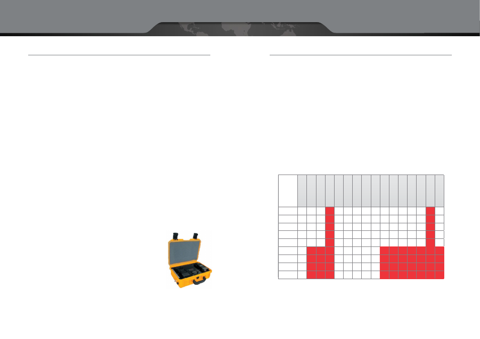
Transportable Radios can be made from two portable (or mobile) radios wired together
in a case as shown in the picture to the right. Here trade-offs in the performance
specifi cations outlined above have been made in favor of cost, size and weight.
Key considerations to bear in mind include:
•
Do I need to transparently pass P25 encryption or P25 control signals?
•
Does the repeater need to operate 100% of the time?
•
Are cost, size and weight overriding factors in the selection criteria?
•
Will the repeater be operated in an environment where it is subjected to many sources of RF interference?
4.2.4 Frequency Bands
The licensed Land Mobile Radio (LMR) spectrum we all use is broken into different frequency bands. These are com-
monly known by the following designators:
•
Lowband
- 29 to 50 MHz
•
VHF
- 136 to 174 MHz — Very High Frequency
•
UHF
- 406 to 520 MHz — Ultra High Frequency
•
700/800 MHz band
- 768 to 869 MHz
Since the frequencies licensed to any given agency are fi xed and the process of obtaining new frequencies from the
FCC is complex, this guide has assumed that the frequencies assigned to your agency are fi xed and will not discuss
the pros and cons of different frequency bands. Suffi ce it to say that the lower the frequency band the greater the
propagation coverage as illustrated in the table below. The higher frequencies (700/800 MHz) shown in red do not
propagate well into a building or through any other type of obstruction (hills or trees).
In-Building Coverage Environments by Frequency
4 = very good coverage
3 = good coverage
2 = average coverage
1 = very limited coverage
0 = poor coverage
25–50
4
3
3
1
4
4
4
4
3
2
4
4
3
2
1
3
138–144
4
3
3
1
4
4
4
4
3
2
4
4
3
2
1
3
148–174
4
3
3
1
4
4
4
4
3
2
4
4
3
2
1
3
406–420
3
2
2
1
3
3
4
4
3
2
3
3
2
2
1
2
450–470
3
2
2
1
3
3
4
4
3
2
3
2
2
2
1
2
764–776
2
1
1
0
2
2
3
3
2
1
2
1
1
1
0
1
794–806
2
1
1
0
2
2
3
3
2
1
2
1
1
1
0
1
806–824
2
1
1
0
2
2
3
3
2
1
2
1
1
1
0
1
851–869
2
1
0
0
2
2
3
3
2
1
2
1
1
1
0
1
Pu
bli
c S
af
et
y
re
qu
en
cy B
an
ds (
M
H
z)
Ru
ra
l S
et
tin
g
(lo
w d
en
se a
re
a)
Su
bu
rb
an S
et
tin
g
(m
ed
iu
m d
en
se a
re
a)
U
rb
an S
et
tin
g
(h
ig
h d
en
se a
re
a)
0 t
o 3
0 f
t
bel
ow g
ro
u
n
d
0 t
o 5
0 f
t
ab
ov
e g
ro
u
n
d
50 t
o 1
0
0 f
t
ab
ov
e g
ro
u
n
d
10
0 t
o 1
50 f
t
ab
ov
e g
ro
u
n
d
Lo
w D
en
si
ty B
u
ildin
gs
M
ed
iu
m D
en
si
ty
Bu
ild
in
gs
H
ig
h D
en
si
ty
Bu
ild
in
gs
Pl
ai
n
G
la
ss
Le
ad
ed
G
la
ss
Fo
il I
n
su
la
ti
on
Co
n
cr
et
e
M
eta
l
Sh
ee
tr
o
ck
ET-4 Polyethylene Case