5 antennas, 1 radiation patterns and types, 1 1/4 wavelength – Codan Radio Transportable Radio Systems User Guide User Manual
Page 20: 2 5/8 wavelength, 3 yagi, 4 omni directional
www.codanradio.com
© Copyright 2015
© Copyright 2015
www.codanradio.com
PAGE 39
PAGE 38
Below is shown the typical specifi cations for two 150 MHz duplexer. Note that the much smaller mobile duplexer
has sacrifi ced a wide frequency range and requires a wide frequency separation in order to fi t in a much smaller
and lighter package.
The following characteristics defi ne how well a duplexer will meet your requirement:
• Frequency Range or Channel Bandwidth –
All duplexers will have an associated amount of available channel band-
width, which indicates how wide the pass band is that allows the signal to go through. This rating is critical
if multiple channels are needed on the repeater. A duplexer with higher Channel Bandwidths is typically larger physi-
cally and will also have higher insertion losses and lower isolation values to make up for the wider frequency range.
Most mobile duplexers used in Transportable Radios have little or no channel bandwidth available due
to their very small size.
• Frequency Separation –
This specifi cation indicates how close the TX and RX frequencies may be to each other. As
frequencies get closer together, duplexers will increase in physical size due to the added fi ltering needed to achieve
acceptable isolation.
• Insertion Loss –
Every duplexer will apply a certain amount of loss to both the incoming and outgoing signals strengths.
• Isolation –
The duplexer will provide the required isolation between the TX and RX frequencies. A duplexer will be
rated for a particular isolation based on a minimum frequency separation.
• Power Rating –
All duplexers are rated to accept a maximum amount of RF power. Typically the smaller the duplexer,
the lower the power rating.
• Frequency vs. Size –
Duplexer size is also related to signal wavelength. As frequencies move from different bands in
the public safety radio spectrum, the wavelength gets smaller. Wavelength is inversely proportional to frequency.
Therefore, duplexers in the lower VHF frequency ranges are MUCH larger than their 800 MHz counterparts.
4.5 Antennas
Antennas are manufactured to operate on a specifi c frequency and should not be altered
in any way. There are three factors of practical importance in the design of an
antenna. These are:
•
Antenna gain
•
Radiation pattern
•
Physical size/construction
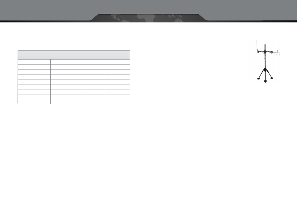
Shown to the right is a rugged collapsible aluminum antenna mast tripod which is ideal
for rapid deployment. The mast is supplied with a duffl e bag with wheels, all necessary
tools, pegs and guy wires. Various heights are available from 2 to 15 metres (6 to 49 feet).
4.5.1 Radiation Patterns and Types
A wide variety of antennas exist to meet different requirements. The photo above illustrates two of the more com-
mon antenna types on the market. On the left is an omni directional 5/8 wavelength monopole and on the right
is directional Yagi.
4.5.1.1 1/4 Wavelength
A quarter wavelength antenna is the simplest of all antenna types. In the 400 MHz band for example it is a very
short (25 cm) monopole antenna. This antenna typically has no gain and is omni directional in nature. The antenna
requires a ground plane for proper operation which is typically 1 wavelength square (approximately 1 square
metre at this frequency).
4.5.1.2 5/8 Wavelength
A 5/8 Wavelength Antenna in the 400 MHz band is a 53 cm long monopole antenna. This antenna typically has low
gain (1–2 dB) and is Omni directional in nature. An example is shown above to the left.
4.5.1.3 Yagi
A YAGI Antenna is still common on most rural rooftops for TV reception. In the LMR frequency bands (UHF and VHF)
the antenna is quite large with an area of several square metres. This antenna typically has good gain (7–8 dB) and is
directional in nature. The size of this antenna dictates a rooftop installation. A signifi cant disadvantage of the YAGI
antenna is the exposed elements of the antenna can create sizeable wind and ice loading. The directionality of the
antenna can also change dramatically under icing conditions. An example is shown above to the right.
4.5.1.4 Omni Directional
An Omni directional antenna is used when the transmitter is located in the center of the desired coverage area. This
type of antenna is widely available at all frequencies. A maximum gain in the range of 12 dBi is possible.
Frequency Range
MHz
132—174
148—157
806—960
Frequency Separation
MHz
0.5
4
3.6
Insertion Loss
dB
1.5
1.4
1.0
Isolation
dB
70
75
70
Power Rating
W
350
50
150
Height
In
4.2
1.5
4.2
Width
In
19
4.5
19
Depth
In
30
7
8
Weight
Lbs
30
2
12
Units
Specifi cation
VHF Fixed
Infrastructure Duplexer
VHF Mobile
Duplexer
800 MHz Fixed Infra-
structure Duplexer
Collapsible Antenna Mast