8 fade margin, 9 path calculation worksheet, 4 duplexers 4.4.1 isolation – Codan Radio Transportable Radio Systems User Guide User Manual
Page 18
www.codanradio.com
© Copyright 2015
© Copyright 2015
www.codanradio.com
PAGE 35
PAGE 34
4.3.8 Fade Margin
The received signal can vary over time due to varying atmospheric conditions, changes in the path profi le resulting in
varying refl ections, diffractions and scattering. To compensate for these variable effects and to ensure reliable path
propagation under all circumstances radio planners introduce a fade margin in the attenuation calculation.
The higher the fade margin the higher the availability of the path under all conditions. A typical fade margin on a Line
of Sight path can be as much as 20–30 dB.
4.3.9 Path Calculation Worksheet
The following table provides a simple worksheet for calculating the signal gains/losses in an LMR radio system and
the resulting margin and range that the system could provide.
4.4 Duplexers
4.4.1 Isolation
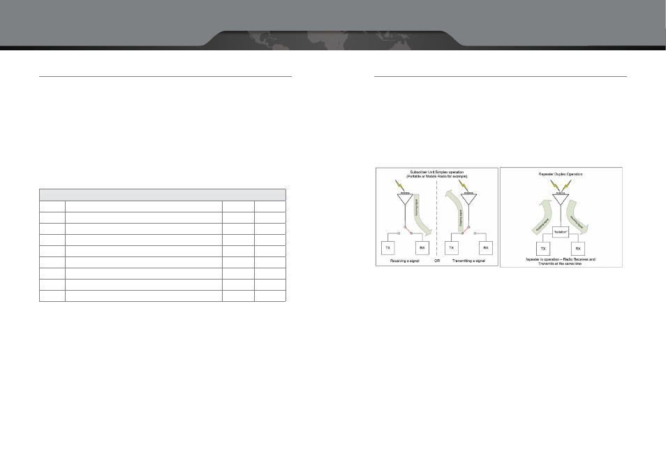
As explained in Section Two, a portable or mobile subscriber unit makes use of simplex operation which allows it to
only receive or transmit a signal, but not both simultaneously. This is accomplished through the use of an antenna
relay that allows the RX to be connected when the radio is receiving signal. When the operator of the radio presses
the Push-to-Talk (PTT) button to transmit a message back, the relay switches over thus disconnecting the receiver
and connecting the transmitter to the antenna.
When we then look at the operation of the Repeater, we can see the difference between simplex and duplex opera-
tion. When a repeater is active, it is both receiving and transmitting signals at the same time. The signal that is being
broadcast by the transmitter will always be MUCH stronger than the incoming receive signal due to the proximity of
the transmitter to the receiver. Because of this, the receiver needs to be isolated from the transmitter to prevent the
strong transmitter signal from interfering with the far weaker incoming signal.
The most important part in creating this isolation is that the transmitter frequency must be different from the
receiver frequency. The greater the difference between the two frequencies, the less likely the transmit signal will
interfere with the receiver. For example, if the receiver frequency is only 500 kHz away from the transmit frequency,
this system will need much more isolation than a system where the receiver frequency is 5 MHz away from the
transmit frequency.
Isolation is measured in dB and every repeater will have a particular isolation requirement that is based on a number
of factors which include:
•
Transmitter Power Output
•
Difference in RX and TX frequencies
•
Frequency Band
•
Selectivity of the receiver
A
Handheld Transmitter
5 W
37
B
Repeater Receiver
118
C
Duplexer Losses
-1.5
D
Cable Losses
-1
E
Antenna
1
F
Obstructions — Trees in a forest
-25
G
Resulting Margin
126.5
H
Desired Fade Margin
-20
J
Resulting Maximum Free Space Loss (420 MHz UHF)
10 Kms
105
RF System Gain Calculation
Value
dB