1 transceivers, 2 duplexers, 3 antenna – Codan Radio Transportable Radio Systems User Guide User Manual
Page 7: Beam antenna
www.codanradio.com
© Copyright 2015
© Copyright 2015
www.codanradio.com
PAGE 13
PAGE 12
2.6.1.1 Transceivers
Transportable Radios can also be built from transceivers which are the same type of radio used in a mobile or por-
table. A transceiver as its name implies (Transmitter/Receiver = Transceiver) is a radio that combines the transmitter
and receiver circuitry together. Compared to a distinct transmitter and receiver pair, a transceiver is a simpler device
offering the benefi ts of smaller size, lower cost and lower current consumption. Hence the reason all portables and
mobiles are transceiver designs. The tradeoff compared with a distinct transmitter/receiver pair is lower performance
specifi cations, lower reliability and having to replace the entire unit in the event of a failure.
2.6.2 Duplexers
As mentioned above, a repeater will always have distinct Transmit and Receive frequencies. Even though the receiver
is designed to ignore signals that are not on its tuned frequency, the transmitter in the repeater will be transmitting
a relatively high strength signal at the same time that the receiver is receiving its signal. To prevent the transmitter
from interfering with the receiver during this “repeat” operation, we need to protect the receiver, or isolate it from
the transmitter.
One way to isolate the Receiver from the Transmitter is to use two separate antennas and place them some distance
apart. How far the antennas need to be away from each other is dependent on the frequency of operation, the power
of the Transmitter and the proximity of the actual Transmit and Receive frequencies. Make no mistake, typically these
two antennas need to be quite a distance apart (tens of meters) in either vertical or horizontal separation.
There is a much easier way to protect the receiver other than running hundreds of feet of cable in opposite direc-
tions! A duplexer can be used to fi lter out the transmitter frequency before the receiver sees it. A duplexer is a radio
frequency fi lter that allows you to connect both the Transmitter and Receiver to a single antenna. The portion that
is connected to the Transmitter will only allow the Transmitters frequency to pass. The portion connected to the
receiver will only allow the receiver frequency to pass. This way the high strength signal created by the Transmitter
cannot be fed back into the Receiver and cause interference or damage the receiver with too much RF power. From a
Transportable Radio standpoint, the duplexer approach makes things much simpler since only a single antenna needs
to be deployed on-scene and it facilitates a compact package.
2.6.3 Antenna
Whether you opt for the dual-antenna deployment or the more commonly used single antenna with a duplexer, pay
careful attention in selecting the right antenna for your application. The antenna receives the signal from the users
in the fi eld and sends out the new repeated signal from the Transportable Radio transmitter.
There are a number of considerations in selecting an antenna:
• Gain –
Antennas can provide gain. This can reduce the amount of RF power needed by the transmitter or it can
increase the coverage range. In Section 4.2.9 we show that for a UHF repeater with a 5 Watt output the expected
coverage range is on the order of 10 kms. To double the coverage distance you need a gain of 6 db or 4 times the RF
output power!
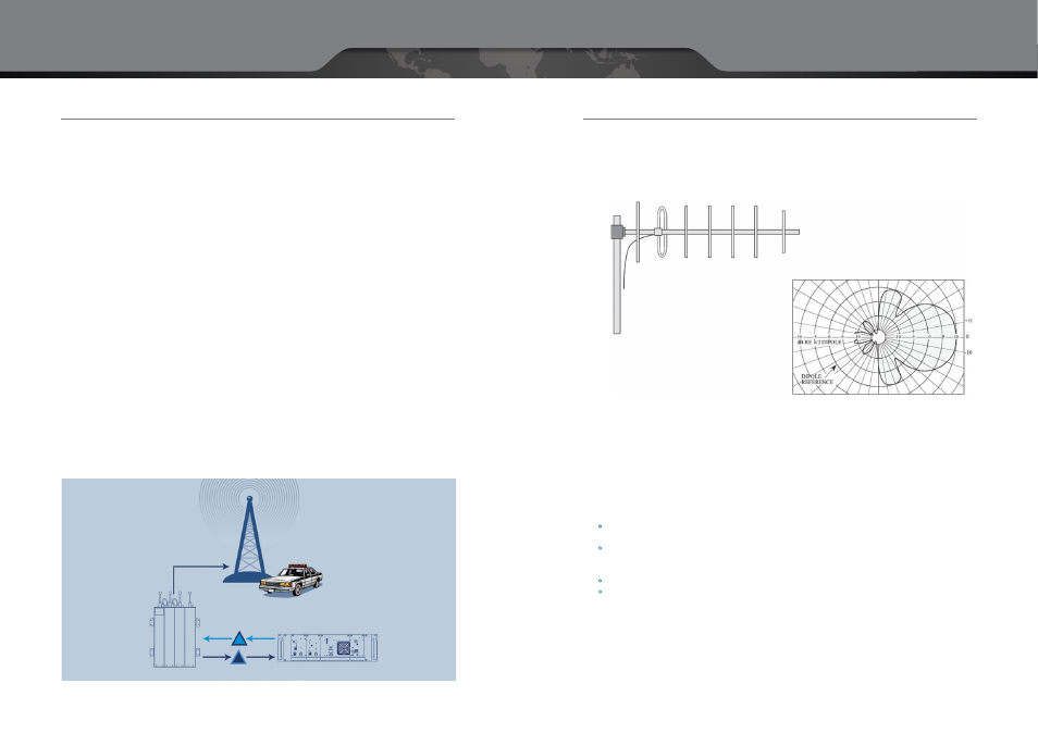
• Radiation Pattern –
antennas can be made to direct the coverage in a specifi c pattern. For example a Yagi antenna
(shown above) will direct most of the signal to the “front” with little or no signal delivered to the sides or back of
the antenna. An Omni directional antenna will radiate in all directions (360°).
• Bandwidth –
The range of frequencies that the antenna is capable of covering.
• Antenna type –
antennas are available in an almost unlimited number of shapes and styles. Common examples include:
The “Rubber Duck” –
a small but convenient antenna, commonly found on portable radios. It has poor transmit
and receive specifi cations but is the easiest to deploy.
Magnetic Mount vehicle antenna –
Assuming a metal surface is handy for mounting this antenna such as the
roof of a car, this can be a convenient antenna for rapid deployment. Has better transmit and receive character-
istics than the Rubber Duck.
Yagi antenna –
requires some form of mast mounting but offers good gain characteristics and is also directional.
Stealth Panel antennas –
are specifi cally designed to be disguised in a case or look like something other then
a radio antenna.
Beam Antenna
Typical Horizontal
Radiation Pattern for
Vertical Polarization
RX — UHF F
2
456.775 MHz
TX — UHF F
1
451.775 MHz
TX — UHF F
1
451.775 MHz
RX — UHF F
2
456.775 MHz
UHF Repeater
Duplexer
Repeater Site
TX — UHF F
1
451.775 MHz
RX —UHF F
2
456.775 MHz
Duplexer enabling connection of
both a transmitter and a reciever
to a single antenna