5 portable antenna, 2 antenna size and characteristics, 3 practical considerations for your antenna – Codan Radio Transportable Radio Systems User Guide User Manual
Page 21: Beam antenna
www.codanradio.com
© Copyright 2015
© Copyright 2015
www.codanradio.com
PAGE 41
PAGE 40
4.5.1.5 Portable Antenna
LMR systems also include mobiles and portables, for which the most common antennas are the “whip” and “rubber-
duck” respectively. Remember that these antennas are also manufactured for use on a specifi c frequency or a narrow
band of frequencies. These antennas are a compromise and provide little or no gain to the signal from the transmit-
ter. Depending on the degree of compromise, they may even show a loss.
4.5.2 Antenna Size and Characteristics
The physical size and construction of the antenna becomes important when you consider the type of housing and
antenna mounting that you will require for your repeater, which in turn is determined by the weather conditions at
your chosen site and the amount of antenna gain your calculations show that you will require.
The gain, shown in dB on the manufacturer’s data sheet, is determined by the construction. However, a gain in one
direction is accompanied by a loss in another direction. Remember when using high gain antennas that the higher
the gain, the smaller the cross-sectional area of the radiation pattern. This is an advantage in links as it reduces the
chance of multiple paths caused by refl ections and is a disadvantage on drops as it will leave near-fi eld shadows.
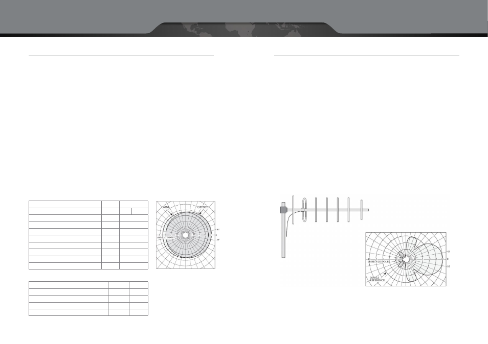
Directional antennas also have the following characteristics — Front-to-back gain ratio greater than 10:1. All antenna
data sheets provide a gain pattern showing the amount of gain provided as a function of the angle. This is usually
referred to as a pattern or polar plot and can be provided both for the horizontal as well as vertical orientations. The
graph below illustrates a typical directional antenna with a 170° horizontal pattern.
Any antenna that you purchase for use on a repeater system will have a nominal impedance of 50 ohms. A VSWR of
1.5:1.0 or less over the frequency range is adequate for transportable purposes.
4.5.3 Practical Considerations for your Antenna
When considering antenna placement think about the antennas that you will be using and watch for surfaces on
either side of the path that may refl ect minor antenna lobes. Watch for near fi eld obstructions when determining
antenna placement.
Where climatic extremes are anticipated, heavy duty models may be necessary. In addition, antennas are manufac-
tured for a rated wind velocity and also for a rated wind velocity with one — half inch of radial ice load. Ensure that
your site conditions are within these limitations. Other factors to consider include:
• Mounting –
How will you mount the antenna?
• Masts –
Can you use a mast?
• Magnetic-Mounts –
Will it mount on a metal surface?
• Ground Planes –
Does the antenna require a large metal fl at surface to act as a ground plane?
• Placement –
Where will the antenna be placed during the deployment? Is stealth a requirement?
• Construction/Environmental considerations –
How robust does the antenna and mast need to be
for your application?
• Icing –
Is this an issue?
• Wind –
Can the wind tip it over?
Frequency Range
MHz
132–174
Nominal Gain
dBd
3
6
Bandwidth, 1.5:1 VSWR
MHz
10
Horizontal Beamwidth (half power points)
Deg
170 (offset)
Vertical Beamwidth (half power points)
Deg
34
Power Rating
W
300
Polarization
Vertical
Pattern
Omni or Offset
Lightning Protection
DC Ground
Termination
Type “N” Male
Omni
Electrical Specifi cations
Offset
Length
mm (in)
2896 (114)
Weight
kg (lbs)
7.7 (17)
Rated Wind Velocity
km/h (mph)
193 (120)
Rated Wind Velocity ( with 0.5 in radial ice)
km/h (mph)
129 (80)
Horizontal Thrust at rated wind velocity and ice load
29.5 (65)
29.5 (65)
Mechanical Specifi cations
Horizontal Radiation Patterns
for Vertical Polarization
Beam Antenna
Typical Horizontal
Radiation Pattern for
Vertical Polarization