1 up converter description – Comtech EF Data KST-2000A/B User Manual
Page 73
Ku-Band Satellite Transceiver
Revision 9
Operation
MN/KST2000AB.IOM
3–25
3.8.1
Up Converter Description
The up converter accepts a 70 MHz (140 MHz) IF input signal and translates it to an out-
put frequency in the range of 13.750 to 14.500 GHz. The up converter consists of two
modules: the IF to S-Band module and the S- to Ku-Band module.
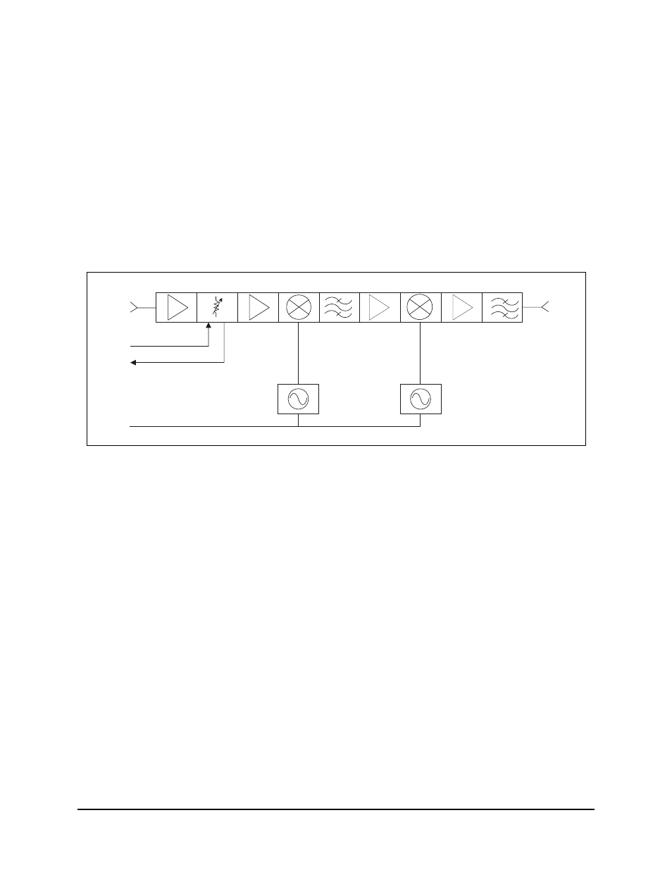
The IF to S-Band module translates the 70 MHz (140 MHz) IF input to an output fre-
quency in the range of 2,330 to 3,080 MHz. Refer to Figure 3-14 for a block diagram of
the IF to S-Band module.
MX1
MX2
70/140
MHZ
GAIN
CONTROL
DETECT
72 MHZ
REF
L01
L02
1035 (70)
960 (140)
3.435-4.185 (70)
3.430-4.180 (140)
2330-
3080
MHZ
Figure 3-10. IF to S-Band Converter Module Block Diagram
The 70 MHz (140 MHz) IF input is first amplified, and then applied to an electronically
variable attenuator. This attenuator is controlled via the local M&C to provide calibrated
1dB attenuation steps over a 20 dB attenuation range. The signal is then amplified and
heterodyned with a fixed frequency LO1. The desired sideband of this process is selected
via bandpass filtering and applied to the second up conversion stage MX2. LO2 is a low
noise synthesized source, whose output covers 750 MHz in 1 MHz steps. The output of
the second up conversion stage is a signal in the 2330 to 3080 MHz frequency range.
This signal is applied to the input of the S- to Ku-Band module.
This module is slightly different for the 70 MHz and 140 MHz IF input options. As
shown in Figure 3-14, the LOs are tuned to different frequencies and filtering is different.