Rs422, Modem, Fiber optic – Daktronics AB-1010 User Manual
Page 22
Electrical Installation
3-6
RS422
Route conduit and cable from the PC running Venus 1500 to the left end of the master display.
Con
u
ble
should b
2).
Drawing A-103727 is an example of the termination block. The other end is terminated at the
sign
oom (as seen in the
following table). Refer to Drawing A-148859 for the correct wire type.
abling
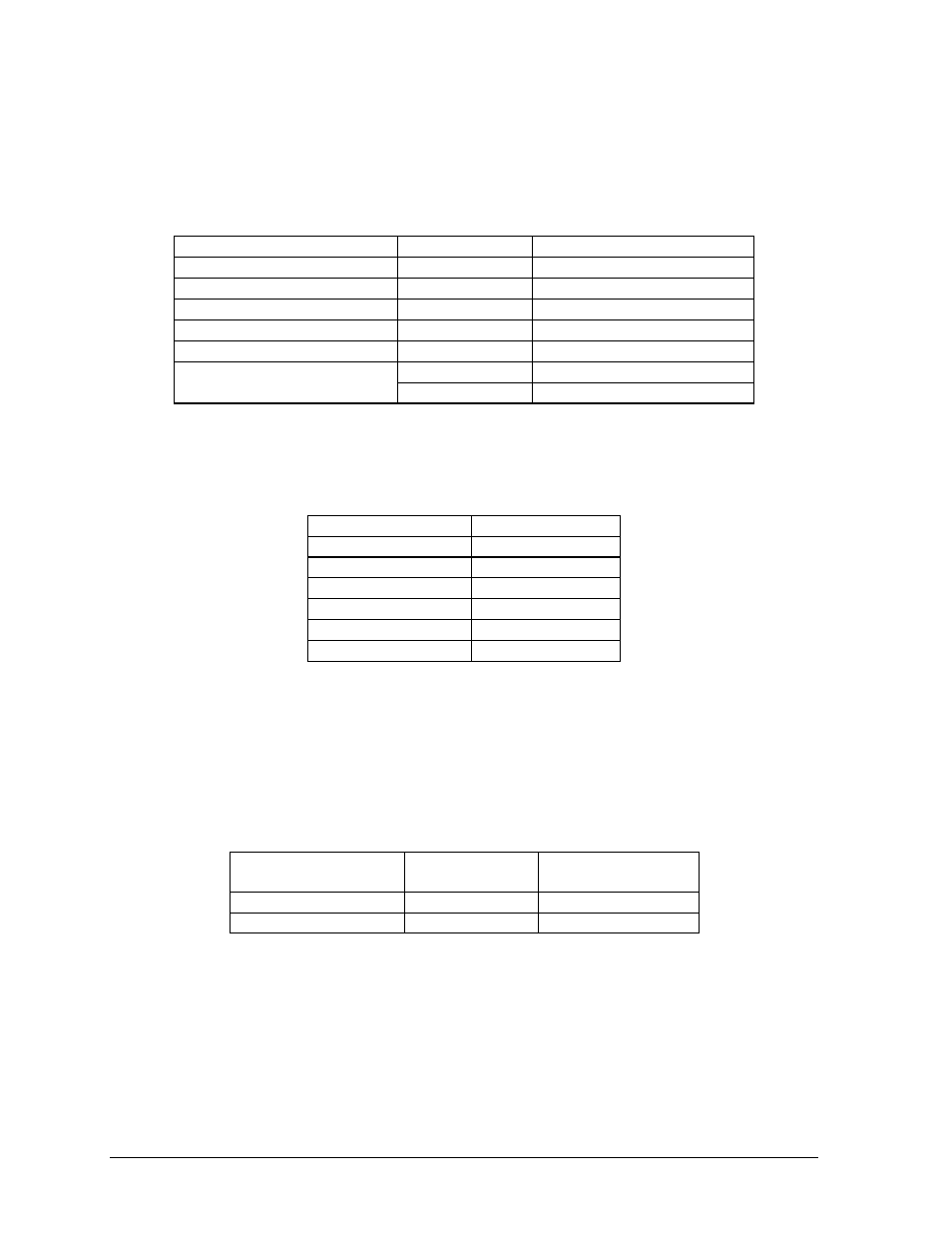
Terminal Block (Data In)
tin e cable into the controller box fitting labeled “Signal In.” One end of the signal ca
e terminated to the 6-position terminal block in the display labeled “RS422 IN” (TB
al converter (Daktronics part number 0A-1127-0237) in the control r
Signal Converter (J4/J5)
Field C
Pin 1 (GND)
Red
Pin 1 (GND)
Pin 2 (RX-P)
Black
Pin 2 (TX-P)
Pin 3 (RX-N)
Brown
Pin 3 (TX-N)
Pin 4 (TX-P)
White
Pin 4 (RX-P)
Pin 5 (TX-N)
Blue
Pin 5 (RX-N)
Green
Pin 6 (GND)
Pin 6 (GND)
Shield (Bare)
N.C.
Modem
Terminate the signal telephone wires to J-1094 as designated on Drawing A-130246. Refer to
Drawing A-148884for the correct wire type.
Telephone Wires
Terminal Block
N.C. Pin
1
N.C. Pin
2
TIP-P Pin
3
Ring-P Pin
4
N.C. Pin
5
N.C. Pin
6
Note: Ask the phone line installer which wire color is “tip” and which is “ring”.
Fiber Optic
Route conduit and fiber cable from the PC to the left end of the master display. Continue routing
be
r cable from the signal converter of the PC to the fiber
ollowing table. Refer to Drawing A-148878for the correct
Field Cabling
fi
r to the controller box. Connect fibe
card in the display as described on the f
wire type.
Signal Converter
Sign A
Data Out (J2 & J3)
Data In (J4 & J5)
J2 (TX1)
J5 (RX2)
J3 (RX1)
J4 (TX2)