Driver/ module numbering system -2 – Daktronics AB-1600-1.5,2.5 User Manual
Page 18
Electrical Installation
3-2
3.1.2 Existing Power Installation
In many cases, displays will be installed where it is advantageous to use an existing
power installation. These existing power installations may not have an earth ground
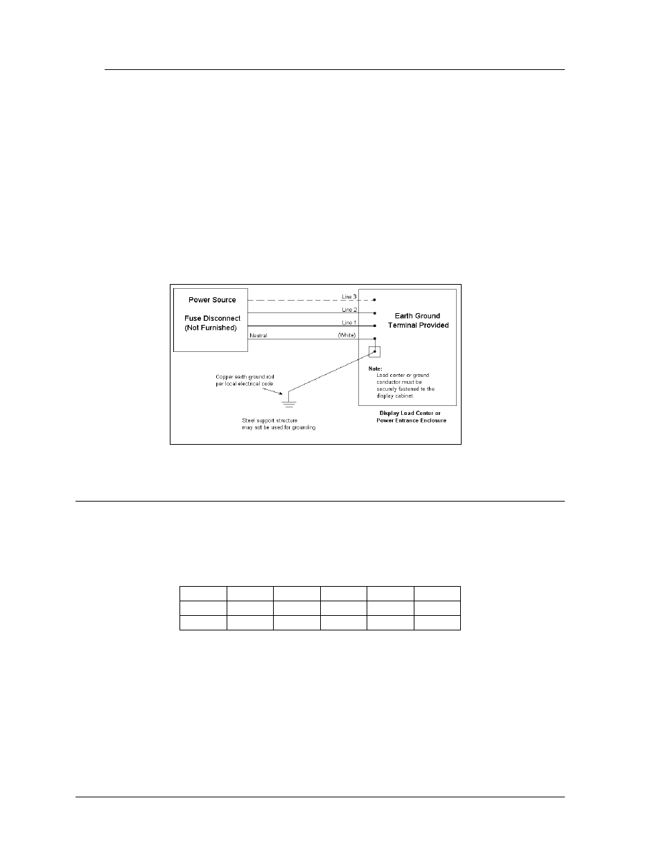
conductor. If this is the situation, the earth grounding should be done as outlined in
Figure 3.
Note that if new power is being pulled to the display, the new power installation
method (Figure 2) using an earth ground conductor from the source is recommended.
The existing power installation method used in Figure 3 is not as effective in
protecting equipment as the method in Figure 2. In Figure 3, the neutral conductor
must be tied to the ground terminal provided in the load center in the power entrance
enclosure. A conductor size equal to the neutral must be ran from the terminal to an
earth ground rod in accordance with local codes.
3.2 Driver/ Module Numbering System
Displays are shipped with the internal signal and power harness connections completed. Each
wire harness is labeled with a number that corresponds to the identification number of the
module(s) to which it is connected. The following table shows an example of the module
numbering system.
A101 A102 A103 A104 A105 A106
A201 A202 A203 A204 A205 A206
A301 A302 A303 A304 A305 A306
•
=
The labeling reference begins with the left module and increments to the right.
•
=
Some signs are multiple-faced. The letter A indicates that module is for sign face “A.”
The letter B would indicate sign face “B,” etc.
•
=
The hundreds digit indicates the display line number. A101 through A106 make up the
first line of the display. A201 through A206 make up the second display line and so on.
=
Figure 3: Existing Power Installation